Method of surveying a track

a track and track technology, applied in the direction of navigation instruments, position fixation, compasses, etc., can solve the problems of time-consuming and laborious task of positioning the two measuring vehicles precisely, and the unnecessary addition of the track section

Inactive Publication Date: 2003-05-22
FRANZ PLASSER BAHNBAUMASCHINEN IND GMBH
View PDF4 Cites 20 Cited by
  • Summary
  • Abstract
  • Description
  • Claims
  • Application Information

AI Technical Summary

Benefits of technology

0010] A measuring method of this kind has the particular advantage that the laser beam emitter does not need to be aligned with respect to an adjacent reference point in a time-consuming manner. Furthermore, the also time-consuming task of positioning the two measuring vehicles precisely at the beginning and end, respectively,

Problems solved by technology

Furthermore, the also time-consuming task of positioning the two measuring vehicles precisely at the beginn

Method used


Image

  • Method of surveying a track
  • Method of surveying a track

Examples


Embodiment Construction

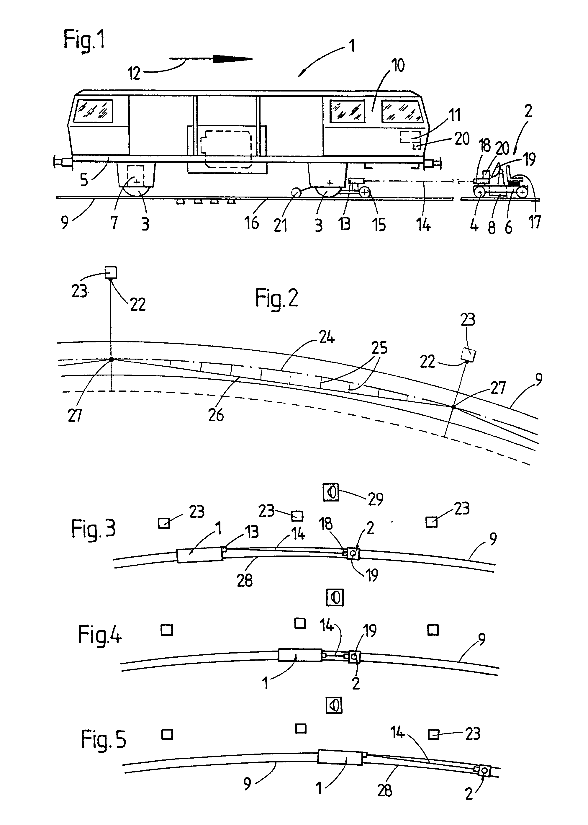
[0015] Throughout all the Figures, same or corresponding elements are generally indicated by same reference numerals.

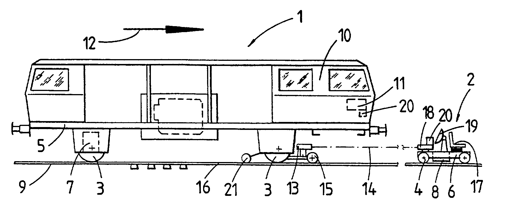
[0016] Referring now to the drawing and in particular to FIG. 1, there is shown a primary machine or measuring vehicle 1 and a satellite or secondary measuring vehicle 2. During track surveying operation, the primary machine 1 is movable relative to satellite or secondary measuring vehicle 2 which remains stationary in place. Therefore, the primary machine is designated hereinafter as mobile measuring vehicle 1 while the satellite is designated hereinafter as stationary secondary measuring vehicle 2. The mobile measuring vehicle 1 has a machine frame 5 which is supported by undercarriages 3 and includes a motive drive 7 for mobility along a track 9 in an operating direction. Likewise, the stationary measuring vehicle 2 has a machine frame 6 which is supported by undercarriages 4 and includes a motive drive 8 for mobility, independently from the mobile measuring vehicl...


PUM


Abstract

In a method of surveying a track (9), a first or mobile measuring vehicle (1) and a second or stationary measuring vehicle (2) are placed at a distance apart from one another on a track section to be measured. A reference line (14) is formed by a laser beam emitted from the stationary measuring vehicle (2). At the start of each measuring cycle, by using a GPS receiver (19), the relative position of the stationary measuring vehicle (2) with reference to a fixedly installed GPS reference station (29) located adjacent to the track section is determined, the said GPS reference station being known within a terrestrial coordinate system. The reference line (14) is aligned with the mobile measuring vehicle (1) on the basis of the determined position data, and the track surveying operation is carried out by advancing the mobile measuring vehicle (1) while changes of the actual track position relative to the reference line (14) are registered.

Description

[0001] The present invention relates, in general, to track survey methods, and more specifically to a method of surveying a track, in which a first and a second measuring vehicle are positioned at end points, respectively, of a track section to be measured during a measuring cycle, the first measuring vehicle being designed for mobility independently of the second measuring vehicle which is stationary during the measuring operation, and the position coordinates of the second measuring vehicle are determined, a reference line in the form of an optical measuring beam is set up between the two measuring vehicles, and the mobile, first measuring vehicle is advanced in the direction towards the stationary, second measuring vehicle while any change in position of a receiving unit, mounted on the first measuring vehicle, relative to the reference line is registered as a correction measurement value.[0002] A method of track surveying with a track pre-measurement car called EM-SAT is describ...

Claims


Application Information

Patent Timeline
IPC IPC(8): E01B27/17E01B35/00G01C15/00G01B5/20G01B11/00G01S1/00G01S5/02G01S5/10G01S5/14G01S17/88G01S19/14G01S19/50G01S19/51
CPCG01S17/88G01S19/51G01S19/14
Inventor THEURER, JOSEFLICHTBERGER, BERNHARD
Owner FRANZ PLASSER BAHNBAUMASCHINEN IND GMBH
Why Eureka
Try Eureka