
System for detecting the characteristics of a time varying multipath component

a multipath component and detection system technology, applied in the field of circuitry in the communication receiver, can solve the problems of slow process, adversely affecting the signal processing performed in the receiver, and more problems for moving objects,

Inactive Publication Date: 2008-04-29
MAGNOLIA LICENSING LLC
View PDF10 Cites 0 Cited by
  • Summary
  • Abstract
  • Description
  • Claims
  • Application Information

AI Technical Summary

Benefits of technology

[0008]A system according to the present invention will compensate for multipath signals by producing a control signal for the adaptive circuitry in the demodulator chain from an estimate of the phase difference between the composite without the time consuming task of repeatedly making adjustments in the adaptive circuitry and measuring the bit rate until the adjustments are optimized, as in the prior art system.

Problems solved by technology

Moving objects present more problems because the magnitude and phase of the multipath signal components from such objects vary over time, sometimes relatively rapidly.
These phase and magnitude differences can adversely affect the signal processing performed in the receiver.
However, this process is slow and not easily adaptable to fast varying multipath components.
In addition, as the settings for the adaptive circuitry in the demodulator chain are varied to find the optimum setting, it is possible for the output of the demodulator chain to experience a relatively high bit error rate, which degrades the subsequent signal processing and becomes perceived by the user.
For example, in an HDTV receiver, this process may introduce artifacts into the image represented by the video component, and / or noise into the sound represented by the audio component, of the received signal which will be perceived by the user.

Method used


Image

  • System for detecting the characteristics of a time varying multipath component
  • System for detecting the characteristics of a time varying multipath component

Examples


Embodiment Construction

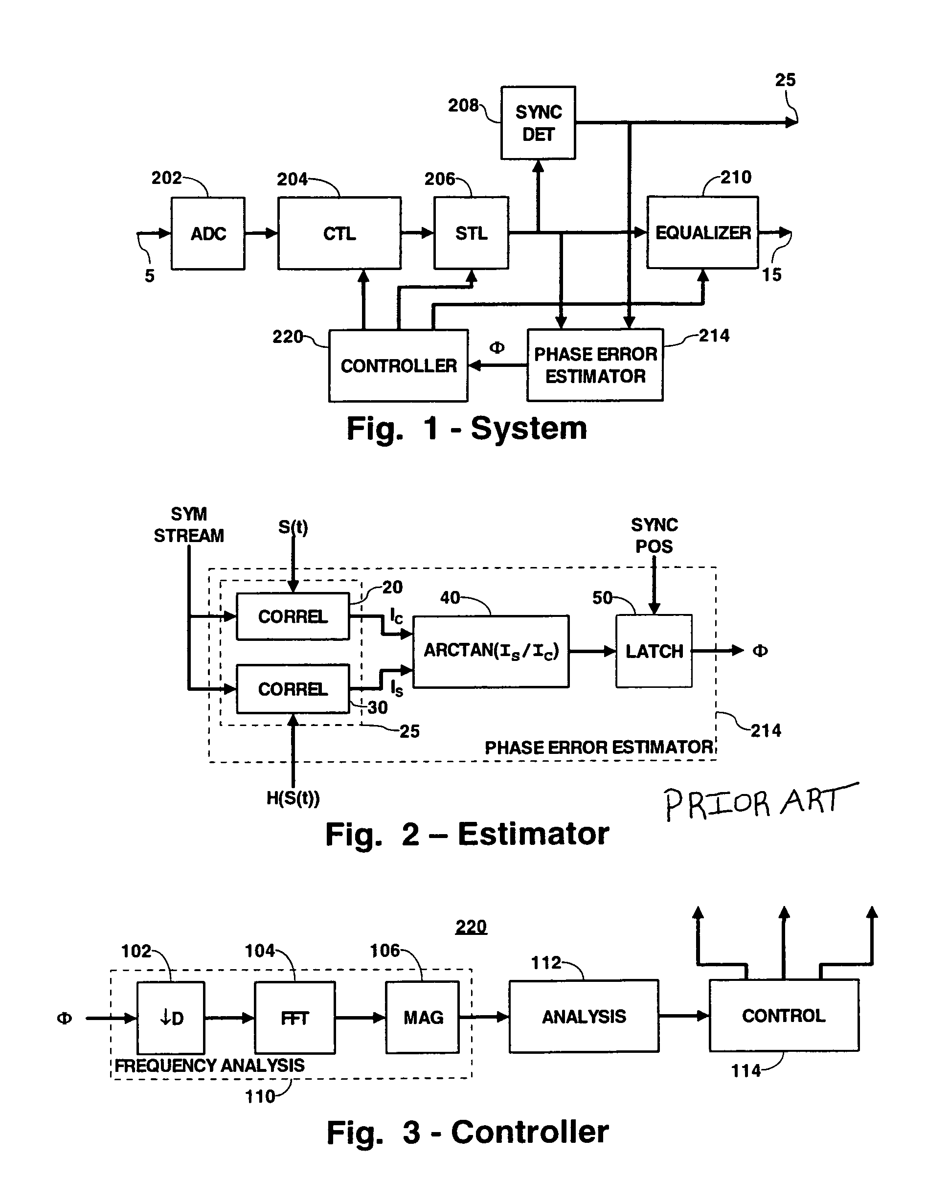
[0013]FIG. 1 is a block diagram of a portion of a receiver including a control signal generator in accordance with principles of the present invention. In FIG. 1, only those elements necessary to understand the construction and operation of the invention are illustrated. One skilled in the art will understand what other elements are necessary, and how to design, construct, and interconnect those elements with those illustrated to make a complete operational receiver.

[0014]In FIG. 1, an input terminal 5 is coupled to a front end (not shown) of a receiver. This front end may include an RF amplifier, detector, and IF amplifier, of known design. The input terminal 5 is coupled to the serial connection of an analog-to-digital converter (ADC) 202, a carrier tracking loop (CTL) 204, a symbol timing loop (STL) 206 and an equalizer 210. An output terminal of the equalizer 210 is coupled to an output terminal 15. The output terminal 15 is coupled to a back end (not shown) of the receiver. Thi...


PUM


Abstract

A system for receiving a composite signal including a main component and a multipath component includes a demodulator chain having adaptive circuitry controllable in response to a control signal to compensate for the multipath component. In this system, a control signal generator includes a phase error estimator, which generates a signal representing an estimate of the phase error between the received main component and the received multipath component. A controller generates the control signal in responsive to the phase error signal.

Description

BACKGROUND[0001]The present invention relates to circuitry in a communications receiver for compensating for the presence of a time varying multipath component in the received signal, and in particular to a system for detecting the characteristics of the time varying multipath component.[0002]In terrestrial broadcast communications systems, signals from a transmitting antenna often arrive at a receiving antenna not only via a direct path from the transmitting antenna to the receiving antenna, but also via one or more other paths due to reflections off of objects in the broadcast area. Signals resulting from such reflections are termed multipath signals. Such objects may be fixed in location, such as buildings, producing a fixed multipath signal. Such objects may also be moving, such as airplanes. Moving objects present more problems because the magnitude and phase of the multipath signal components from such objects vary over time, sometimes relatively rapidly.[0003]When one or more...

Claims


Application Information

Patent Timeline
Patent Type & Authority Patents(United States)
IPC IPC(8): H04B7/10H04B1/10H04N5/21H04B7/005H04J11/00H04N7/015H04N17/00
CPCH04B1/1081H04N7/015
Inventor BOUILLET, AARON REEL
Owner MAGNOLIA LICENSING LLC
Learn More