Ligament fixing system

a fixing system and ligament technology, applied in the field of ligament fixing system, can solve the problems of increasing the invasiveness of the patient, affecting the healing effect of patients, and destroying bone tissue at the time of staple removal

Inactive Publication Date: 2004-04-15
KOSEKI TOMOAKI
View PDF21 Cites 1262 Cited by
  • Summary
  • Abstract
  • Description
  • Claims
  • Application Information

AI Technical Summary

Problems solved by technology

The conventional double stapling method catches the tissue with the two legs of the staple fixed on the tissue, and therefore could easily produce staple site pain (pain caused by the staples).
Also, as the two staples generate some volume sunk within the tissue, there is more invasiveness to the patient.
In cases of ACL (anterior cross ligament) and such, the presumption is that the staples will be removed after the ligament is rebuilt, but with the double stapling method, the bone tissue is often destroyed at the time of staple removal as the staple leg parts catch the bone tissue.
When fixing an end of a ligament with a multiple number of staples, the perpendicular angle is measured at a rough estimate wherein a certain angle of the staples is difficult to be maintained, thus difficult to obtain efficient fixing force.
The bone surface is in a column form and is also slippery.
When staples are fixed in situations with the staple's horizontal parts or its leg parts caught part of the way, the staple ends easily slip on the bone surface, the leg parts of the staple widens easily, thus the driving angle cannot be maintained in a certain angle, a situation which hinders stable driving of the staples.
The cut-shave processing manufacturing method takes much time and labor, and is also costly.
Also products made per the manufacturing method have difficulties in coping with complex curved surface.

Method used


Image

  • Ligament fixing system
  • Ligament fixing system
  • Ligament fixing system

Examples


Embodiment Construction

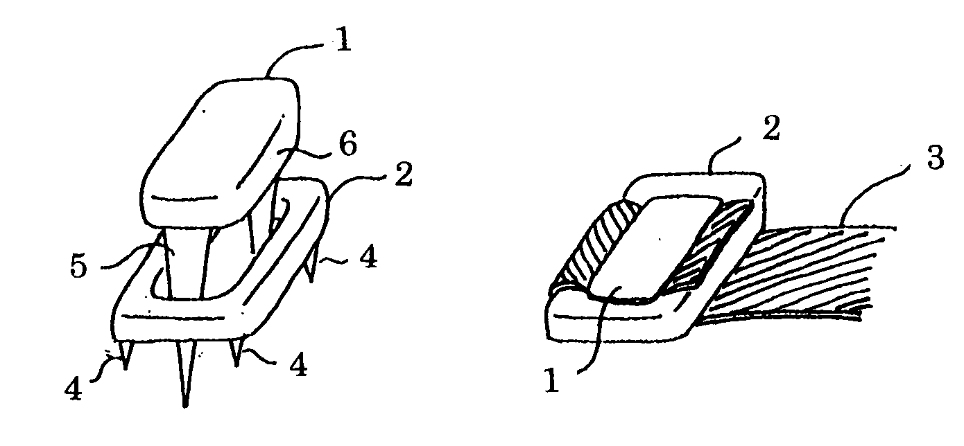
[0020] Hereafter, explanation of the realization of this invention is made in reference to drawings. FIG. 1 shows the fixing system of combining Staple 1 and Plate 2 according to claim 1. The bottom part of Plate 2 has Spikes 4 on the Plate's four corners, the Spikes temporarily fix Ligament 3 on the bone surface, and the central part of the plate has holes. Ligament 3 is folded up in the opposite direction from the originally pulled direction, and when Staple 1 is driven, the two Legs 5 of Staple 1 reach the bone surface through the hole parts of Plate 2, the bottom of the Horizontal part 6 of Staple 1 presses the Ligament 3 onto the bone surface, and will fix Ligament 3.

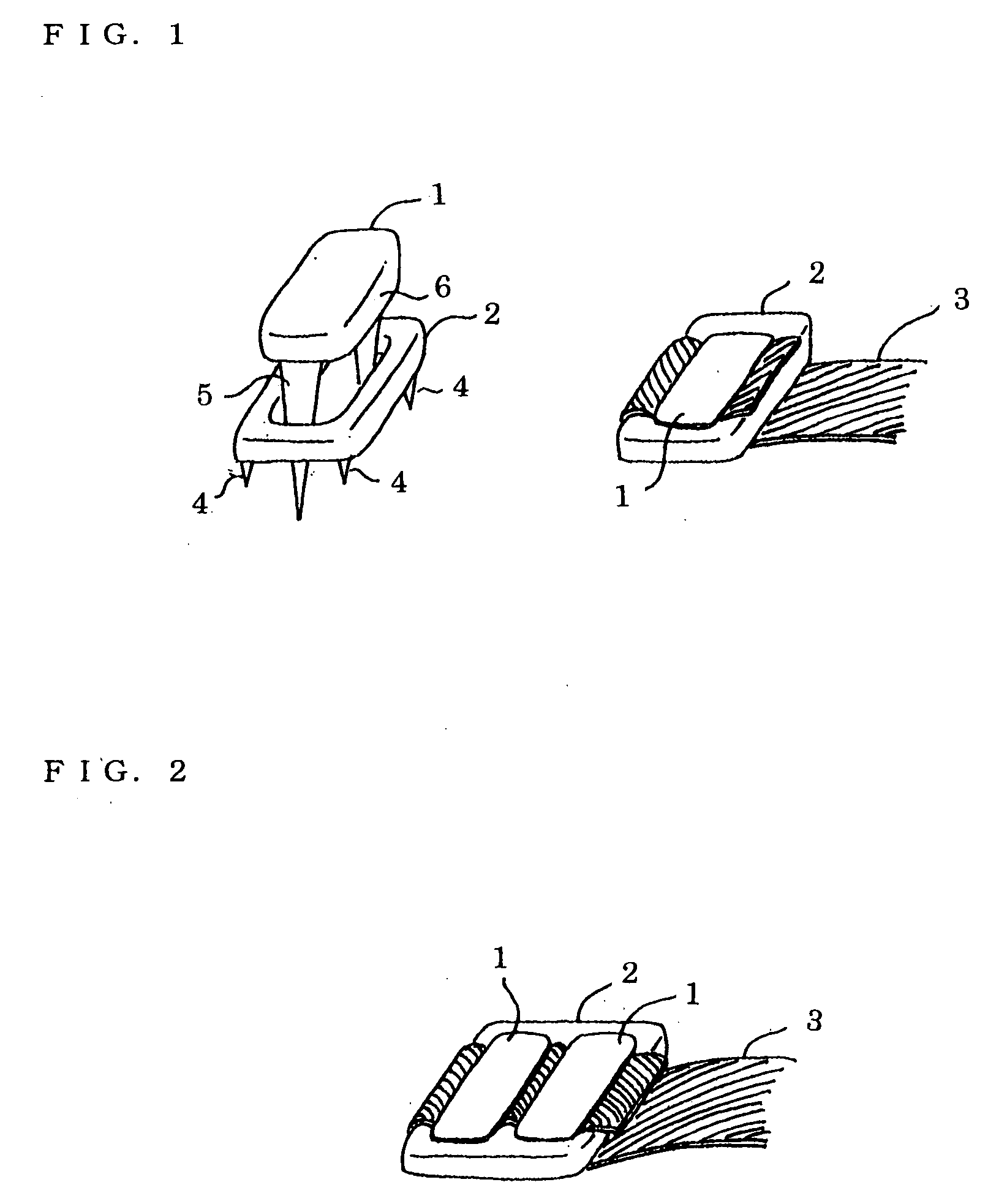
[0021] FIG. 2 shows the type according to claim 2, the type of which has two rows of holes in the plate center aligned along the longitudinal direction of the plate. By driving two staples, the ligament can be fixed with stronger fixing force.

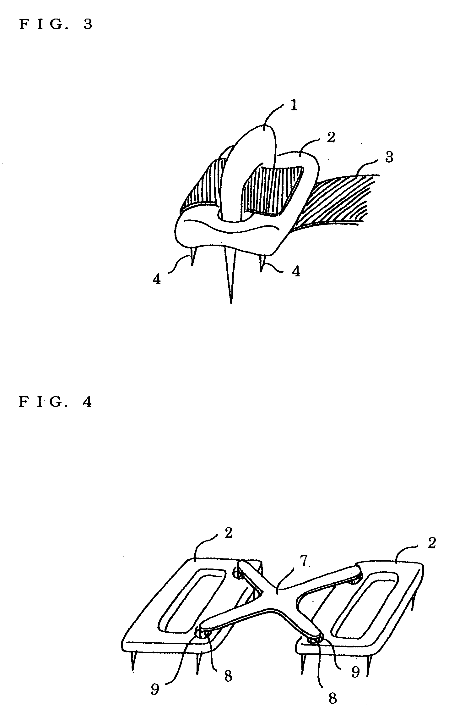
[0022] FIG. 3 shows the type according to claim 3, the plate type of whic...


PUM


Abstract

An inexpensive ligament fixing system capable of providing an efficient fixing force and accurately driving a staple with less invasion, comprising a flat-shaped plate having a plurality of drilled holes and curved bottom and upper surfaces and formed by casting and a cross bar used to allow a parallelism, to be checked, wherein the plate is fixed to a ligament and the folded-up ligament is further fixed with the staple, the tips of the leg parts of the staple are moved from the centerline to the inside, a cut-in is provided on the insides of the leg parts, the cross sections of the leg parts are formed in a polyhedron, the plate is pressed and driven by a driving device having a driving structure by a thrust bar is used.

Description

[0001] This invention is related to the fixing system combining a staple and a plate to fix a ligament on a bone surface, the system of which is utilized during a ligament repair operation.PRIOR ART[0002] A common method to fix a ligament, is the so called Double Stapling method in which the ligament is folded up in the opposite direction after fixing the ligament with one staple, and the second staple is fixed on top of the folded-up ligament in proximity to the first staple. Also, to provide stronger fixing force, there are cases where a multiple number of staples are fixed within some space at one end of the same ligament.[0003] The sharp tip end of the staple is on the center line of the staple leg part. Furthermore, the cross-section of the staple leg part is either round or square.[0004] A driving device to fix the staple has the structure of either holding the horizontal part of the staple or picking and then holding the middle part of the staple leg part, and then the latter...

Claims


Application Information

Patent Timeline
Patent Type & Authority Applications(United States)
IPC IPC(8): A61B17/04A61B17/064A61B17/068A61B17/072A61B17/56
CPCA61B17/0401A61B17/0642A61B2017/0641A61B17/0682A61B17/0643
Inventor KOSEKI, TOMOAKI
Owner KOSEKI TOMOAKI
Why Eureka
Try Eureka