Friction clutch

a clutch and friction technology, applied in the field of friction clutches, can solve the problem of fast continuous axial load on the crankshaft bearings

Inactive Publication Date: 2004-05-06
ZF SACHS AG
View PDF5 Cites 10 Cited by
  • Summary
  • Abstract
  • Description
  • Claims
  • Application Information

AI Technical Summary

Benefits of technology

[0010] In an alternative, very easy-to-implement method for holding the bearing arrangement in place in both axial directions, it is possible for the bearing arrangement to be supported on the housing arrangement in both axial directions by a plurality of pin-like support elements.
[0013] The bearing arrangement can include, for example, a sliding bearing arrangement, where a first sliding bearing element is supported axially on a first retaining element, and a second sliding bearing element is supported axially on a second retaining element. At least one of these sliding bearing elements can simultaneously have a radial support area for the purpose of radial centering. The sliding bearing can run wet or dry; if it runs wet, a seal can be provided. If a wet-running sliding bearing arrangement is used, a sealing arrangement can preferably be provided to encapsulate the bearing arrangement in an essentially lubricant-tight manner. It is therefore possible to supply lubricant to the area of the surfaces which are in frictional contact with each other via one of the components to be supported, so that a very low-friction support can be achieved and so that simultaneously a sealing function at least effective enough to prevent all but slight leaks can be obtained by means of the sealing arrangement.

Problems solved by technology

This leads to a nearly continuous axial load on the crankshaft bearings, which are usually not designed to handle such loads.

Method used


Image

  • Friction clutch
  • Friction clutch
  • Friction clutch

Examples


Embodiment Construction

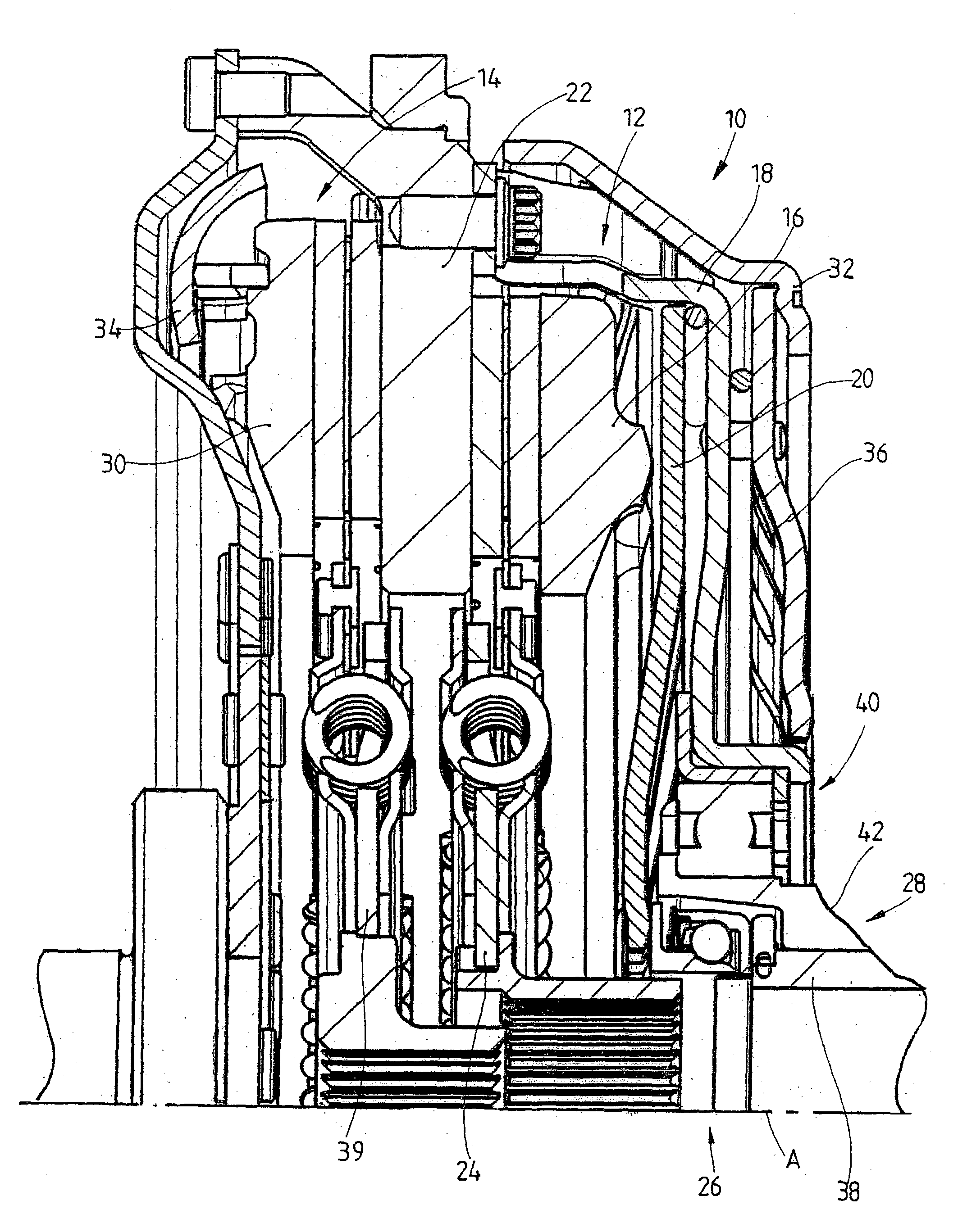
[0027] In FIG. 1, a friction clutch 10 is dual clutch having two clutch areas 12, 14. The first clutch area 12 has a pressure plate 16, which is mounted non-rotatably in a housing arrangement 18, but which has a certain freedom of movement in the direction parallel to an axis of rotation A. The pressure plate 16 can be pushed toward an intermediate plate 22 by a force-exerting arrangement 20, the radially outer area of which is supported on the housing arrangement 18, with the result that the friction linings of a clutch disk 24 are clamped between the pressure plate 16 and the intermediate plate 22. The force-exerting arrangement 20 can comprise several lever elements, which are arranged in the circumferential direction around the axis of rotation and which extend essentially in the radial direction. The lever elements can be connected to each other and can be acted upon in the radially inner area by an actuating mechanism 28, which acts by way of an actuating bearing 26. An energy...


PUM


Abstract

A friction clutch includes a housing having an axis of rotation; a pressure plate connected to the housing for rotation in common; a force exerting arrangement supported against the housing and the pressure plate; an actuator mechanism which acts on the force exerting arrangement to load the pressure plate axially with respect to the housing; and a bearing arrangement for supporting the actuator mechanism axially with respect to the housing so that it is prevented from moving in either axial direction.

Description

[0001] 1. Field of the Invention[0002] The present invention relates to a friction clutch, that includes a pressure plate connected to a housing arrangement for rotation in common around an axis of rotation and a force-exerting arrangement supported against the pressure plate and the housing arrangement.[0003] 2. Description of the Related Art[0004] In these types of friction clutches, the forces and the forces of reaction produced during actuation processes are transmitted to the bearings of a drive shaft such as, for example, to the crankshaft bearings, unless internal support is provided in the friction clutch itself. In the case of conventional clutches, in which energy-storing devices are used as force-exerting arrangements and the actuating processes leading to the forces in question are clutch-release processes, the loads exerted on the crankshaft bearings are comparatively short in duration. In the case of clutches which are kept engaged by the production of a continuous eng...

Claims


Application Information

Patent Timeline
Patent Type & Authority Applications(United States)
IPC IPC(8): F16D21/06
CPCF16C35/077F16D21/06F16C2361/43F16D2021/0684F16C35/067F16D2021/0607F16C35/02F16C17/10F16C19/06
Inventor ORLAMUNDER, ANDREASPAGELS, OLAFKLEUKER, CHRISTOPHHEIARTZ, MARKUSVOGT, SEBASTIAN
Owner ZF SACHS AG
Why Eureka
Try Eureka