Measuring cable travel sensor with longitudinal drive for the cable drum

a technology of measuring cable and travel sensor, which is applied in the direction of mechanical measuring arrangement, hoisting equipment, instruments, etc., can solve the problems of limited resolution of the measuring cable travel sensor, limited maximum possible length of the measuring cable, and additional difficulty

Inactive Publication Date: 2003-05-13
ASM AUTOMATION SENSORIK MESSTECHN GMBH
View PDF19 Cites 58 Cited by
  • Summary
  • Abstract
  • Description
  • Claims
  • Application Information

AI Technical Summary

Problems solved by technology

In that respect there is an additional difficulty insofar as such measuring cable travel sensors often have to be used in an adverse environment, for example involving a high level of fouling and contamination.
Even if the diameter of the cable drum is selected to be relatively large to provide a compensatory effect, that nonetheless entails a limitation in terms of the maximum possible length of the measuring cable.
In addition, that affords a structural configuration which is very large in the radial direction, and a single revolution of the cable drum corresponds in that case to a relatively long peripheral length and thus a relatively long length of cable, so that the level of resolution of the measuring cable travel sensor is restricted in consequence.
A disadvantage with those structures however is that the degree of longitudinal displacement depends on the pitch of the screwthread on the screwthreaded spindle and the spindle nut co-operating therewith.
This can scarcely be effected on site even by a specialized fitter, quite apart from the large amount of time that this necessarily entails.
That would also remove the compulsion for the provision of at least a pair of braking magnets on the cable drum, as a single magnet results in a cable drum unbalance, and that arrangement also makes available more space for example for fitting a magnet holder for adjustability of the air gap.

Method used


Image

  • Measuring cable travel sensor with longitudinal drive for the cable drum
  • Measuring cable travel sensor with longitudinal drive for the cable drum
  • Measuring cable travel sensor with longitudinal drive for the cable drum

Examples


Embodiment Construction

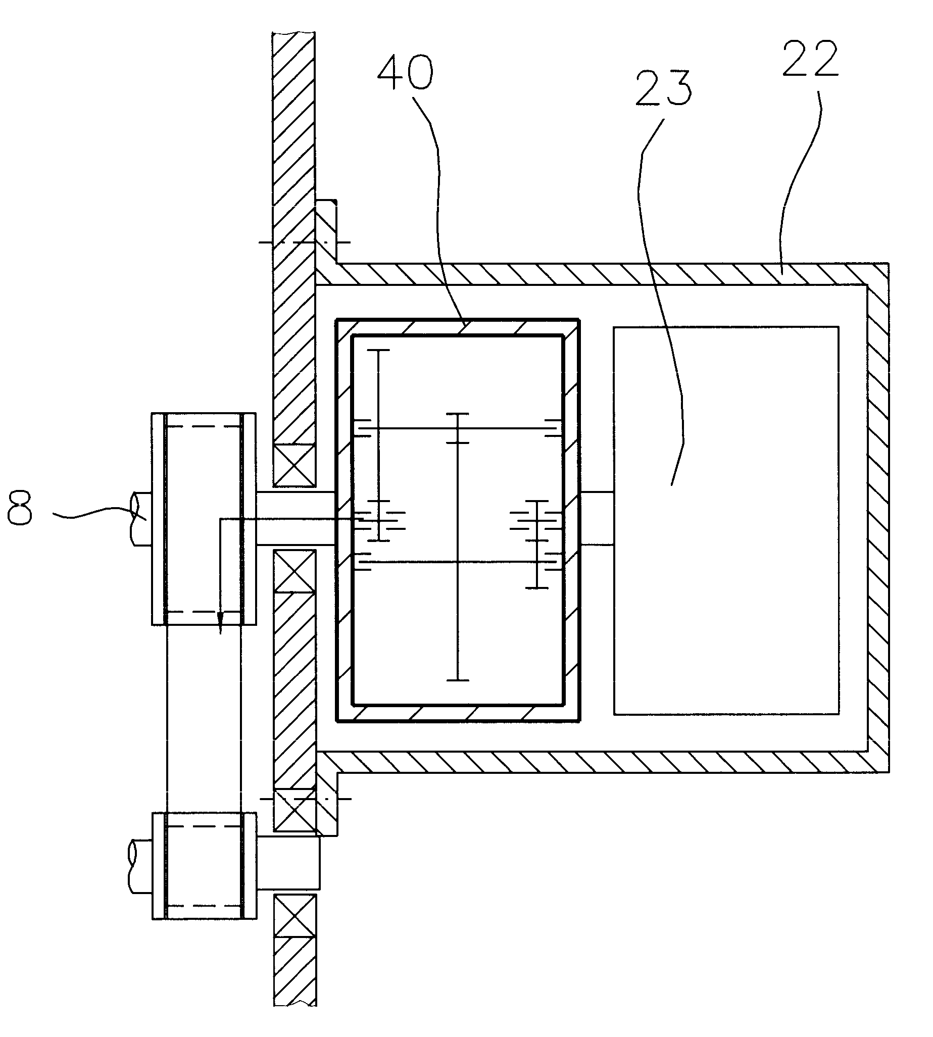
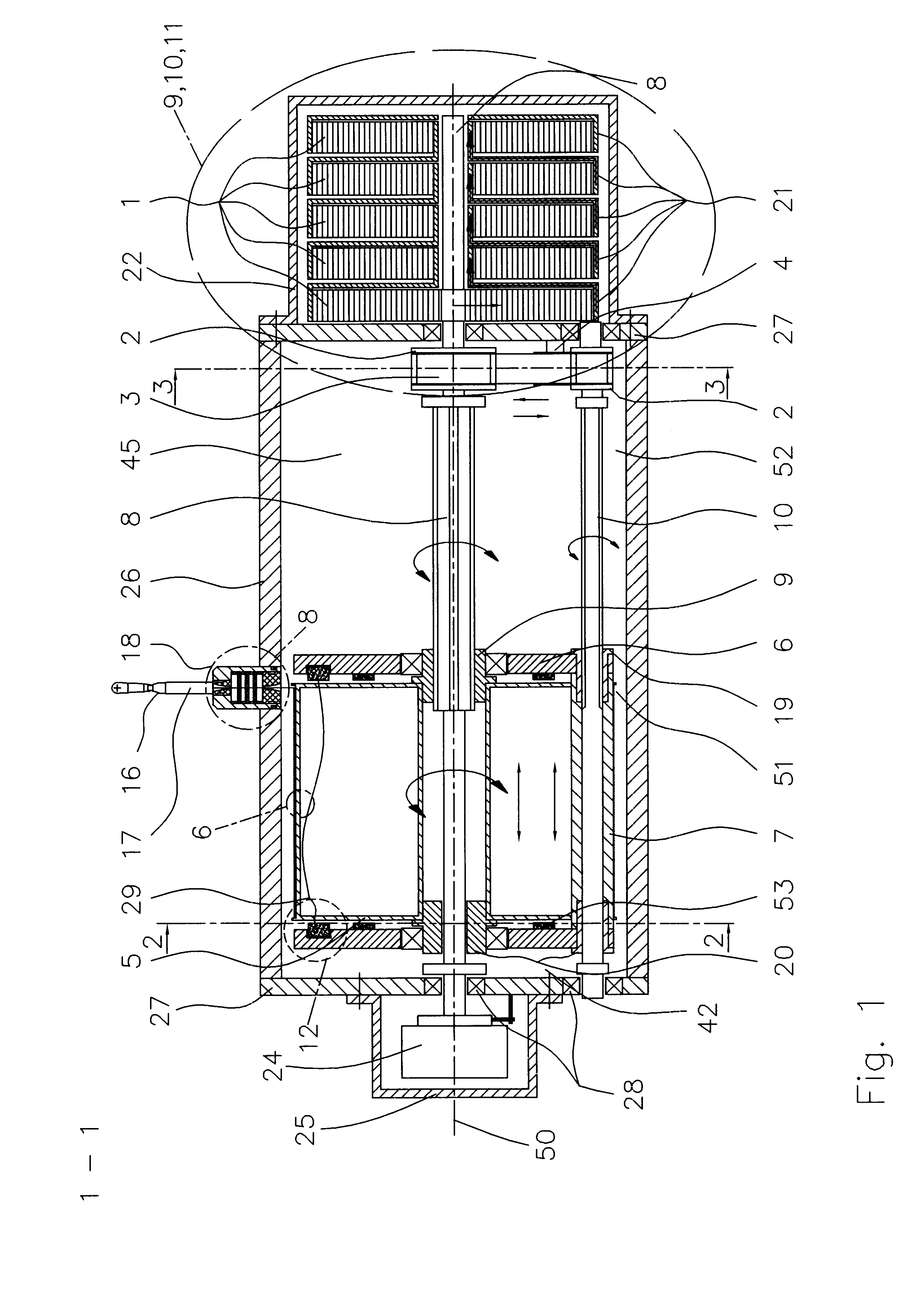
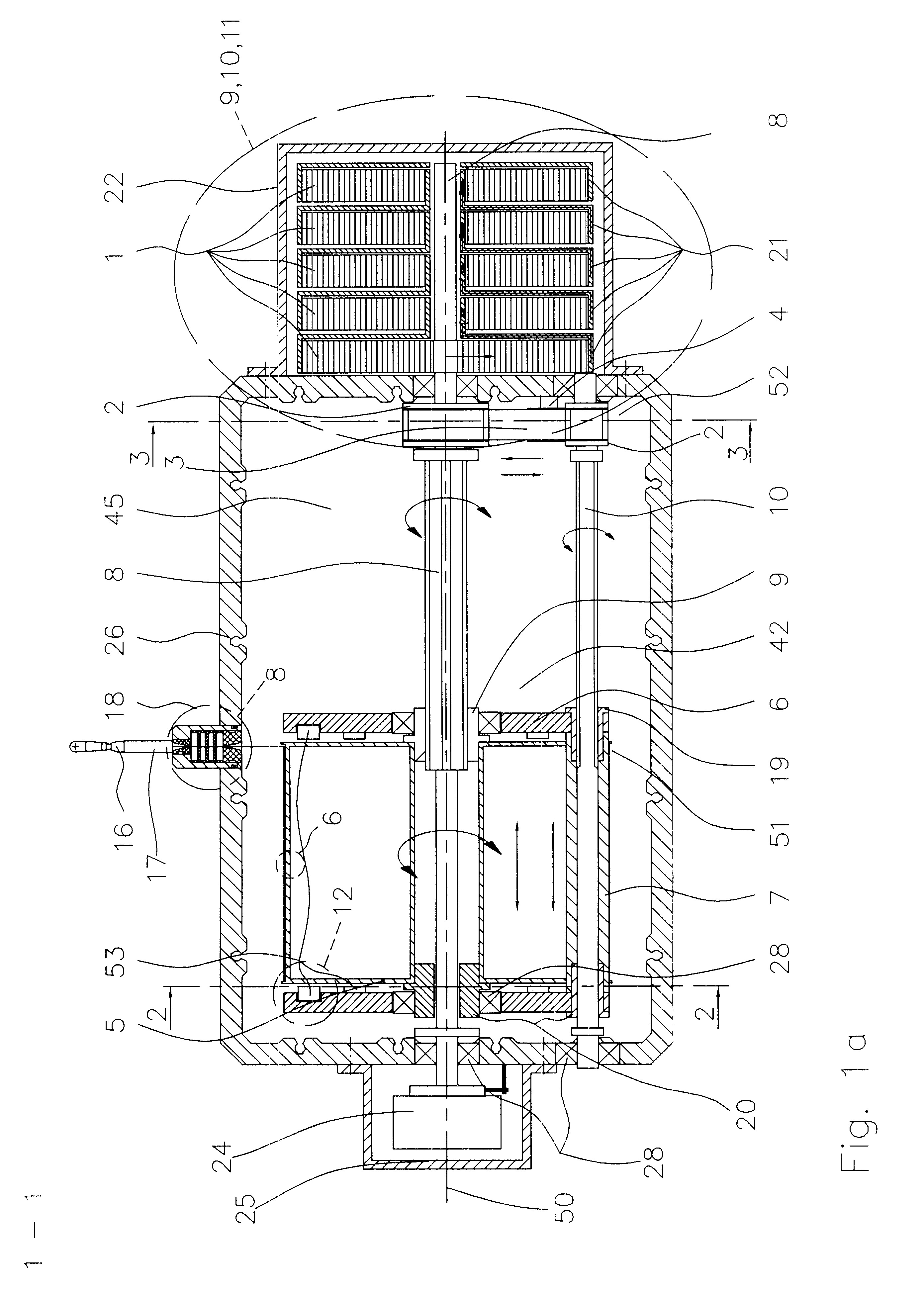
Reference will now be made generally to FIGS. 1 through 1c showing embodiments of a measuring cable travel sensor according to the invention in section taken along a longitudinal direction thereof as indicated at 50, which coincides with the axis of rotation of a central shaft 8 on which a cable drum 5 is longitudinally displaceably but non-rotatably mounted. The shaft 8 passes outwardly through each of respective end plate portions 27 which, together with a closed shaped member 26, form a central housing of the travel sensor. Arranged at one end, being the left-hand end in for example FIG. 1, on the central shaft 8 which is also supported in the end plate portions 27, is a rotary angle sensor 24. The sensor 24 is non-rotatable with respect to the main housing member 26 and is covered by means of a generally cup-shaped sensor housing 25. The sensor housing 25 is fixed by the open edges thereof to the left-hand end plate portion 27 of the main housing member 26, in particular by scre...


PUM

PropertyMeasurementUnit
rotational movementaaaaaaaaaa
axis of rotationaaaaaaaaaa
displacementaaaaaaaaaa

Abstract

A measuring cable travel sensor includes a housing and a cable drum which is arranged in the housing rotatably and longitudinally displaceably in the longitudinal direction of the travel sensor. The measuring cable is guided into and out of the housing through a stationary cable guide. The travel sensor has a longitudinal drive for displacing the cable drum, including a spindle drive comprising a screwthreaded spindle and a spindle nut screwable thereon. The longitudinal drive has an additional transmission for transmitting rotary movement of the cable drum to the spindle drive for producing cable drum displacement.

Description

1. Field of the InventionThe invention concerns a measuring cable travel sensor and more particularly a measuring cable travel sensor having a longitudinal drive for displacement of the cable drum.2. Background of the InventionMeasuring cable travel sensors occur in many different configurations for example for determining the precise position of a given component which in particular can move over considerable travel distances, for example the cabin of an elevator. A typical measuring cable travel sensor of that kind and for that purpose has a pull element such as a measuring cable which is wound on a cable drum which is biassed in the cable winding-on direction. The free end of the measuring cable is connected to that component whose position is to be determined, for example as mentioned above an elevator cabin. The prestressing force for urging the cable drum in the winding-on direction is produced for example by way of a flat spiral spring which for example is arranged coaxially ...

Claims


Application Information

Patent Timeline
Patent Type & Authority Patents(United States)
IPC IPC(8): B65H75/38B65H75/42B65H75/44B66B11/00G01B7/02G01B3/11
CPCB65H75/42B65H75/4413B65H75/4442G01B7/026B66B11/0075G01B3/11B65H2301/5115B65H2403/61B65H2555/13B65H2701/34B65H2701/35B65H2403/7254
Inventor STEINICH, KLAUS-MANFRED
Owner ASM AUTOMATION SENSORIK MESSTECHN GMBH
Why Eureka
Try Eureka