Wiper blade provided with detachable blade rubber and wiper system having the same
a technology of wiper blade and blade rubber, which is applied in the direction of vehicle maintenance, vehicle cleaning, domestic applications, etc., can solve the problems of deteriorating the appearance of the wiper blade, increasing the replacement cost of the blade rubber, and difficult for an ordinary user to bond the blade rubber
- Summary
- Abstract
- Description
- Claims
- Application Information
AI Technical Summary
Problems solved by technology
Method used
Image
Examples
first embodiment
[0030] the present invention will be described with reference to the accompanying drawings.
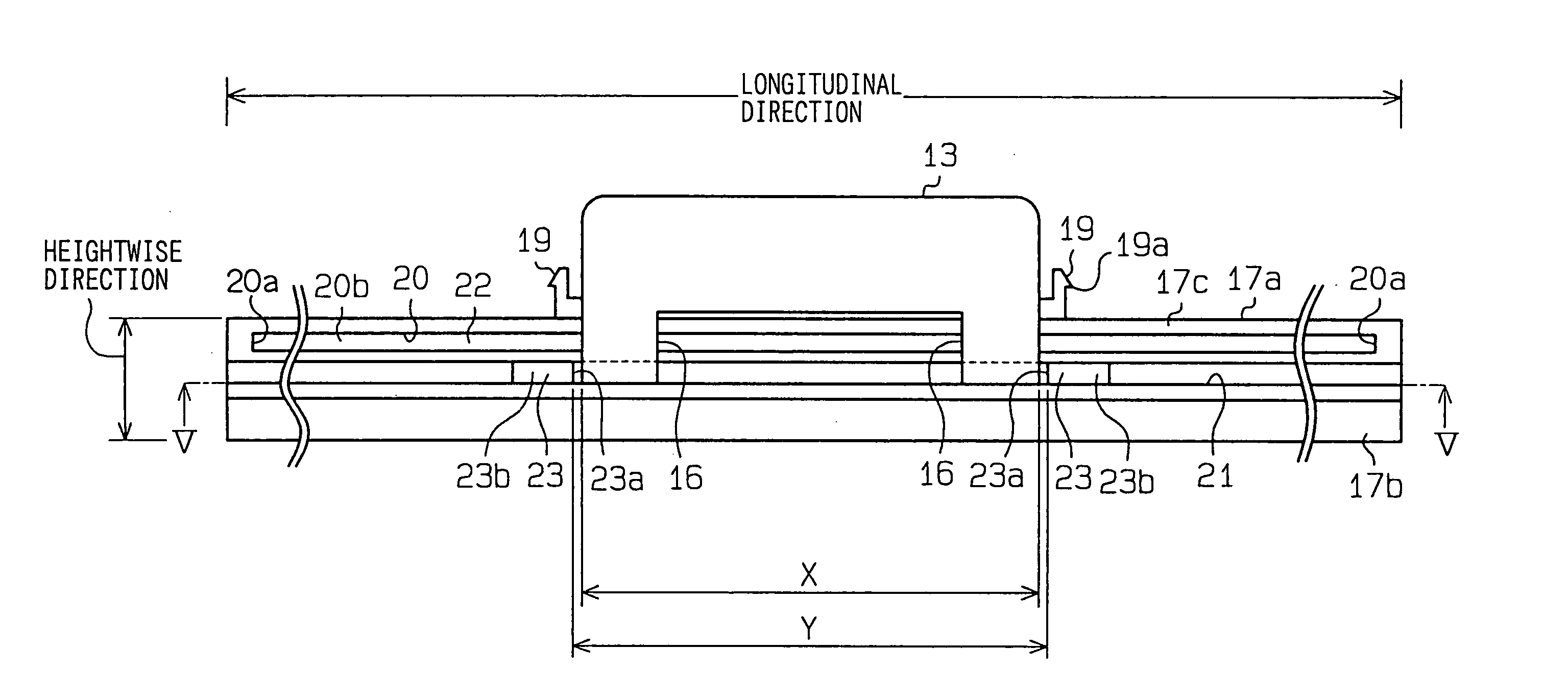
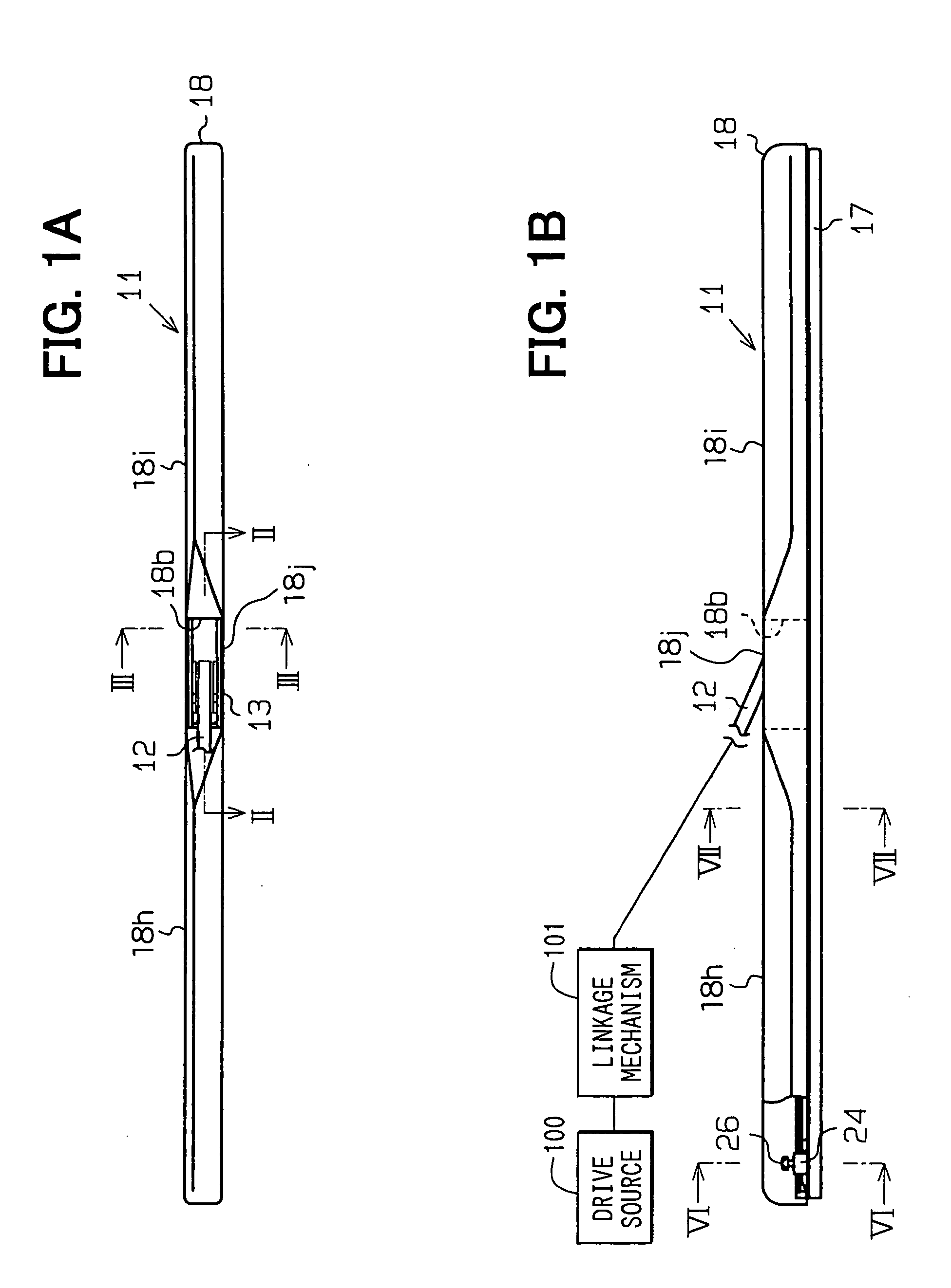
[0031] With reference to FIGS. 1A and 1B, a wiper blade 11 of a wiper system according to a first embodiment of the present invention is rotatably connected to a wiper arm 12 and is urged by the wiper arm 12 against a windshield surface 27 (FIG. 7) to be wiped. The wiper system of the present embodiment includes at least one such wiper blade 11, at least one such wiper arm 12, a drive source (such as an electric motor) 100 and a linkage mechanism 101, which links between the drive source and the wiper arm 12. The windshield surface 27, which is wiped by the wiper blade 11, serves as a wiping surface of the present invention.
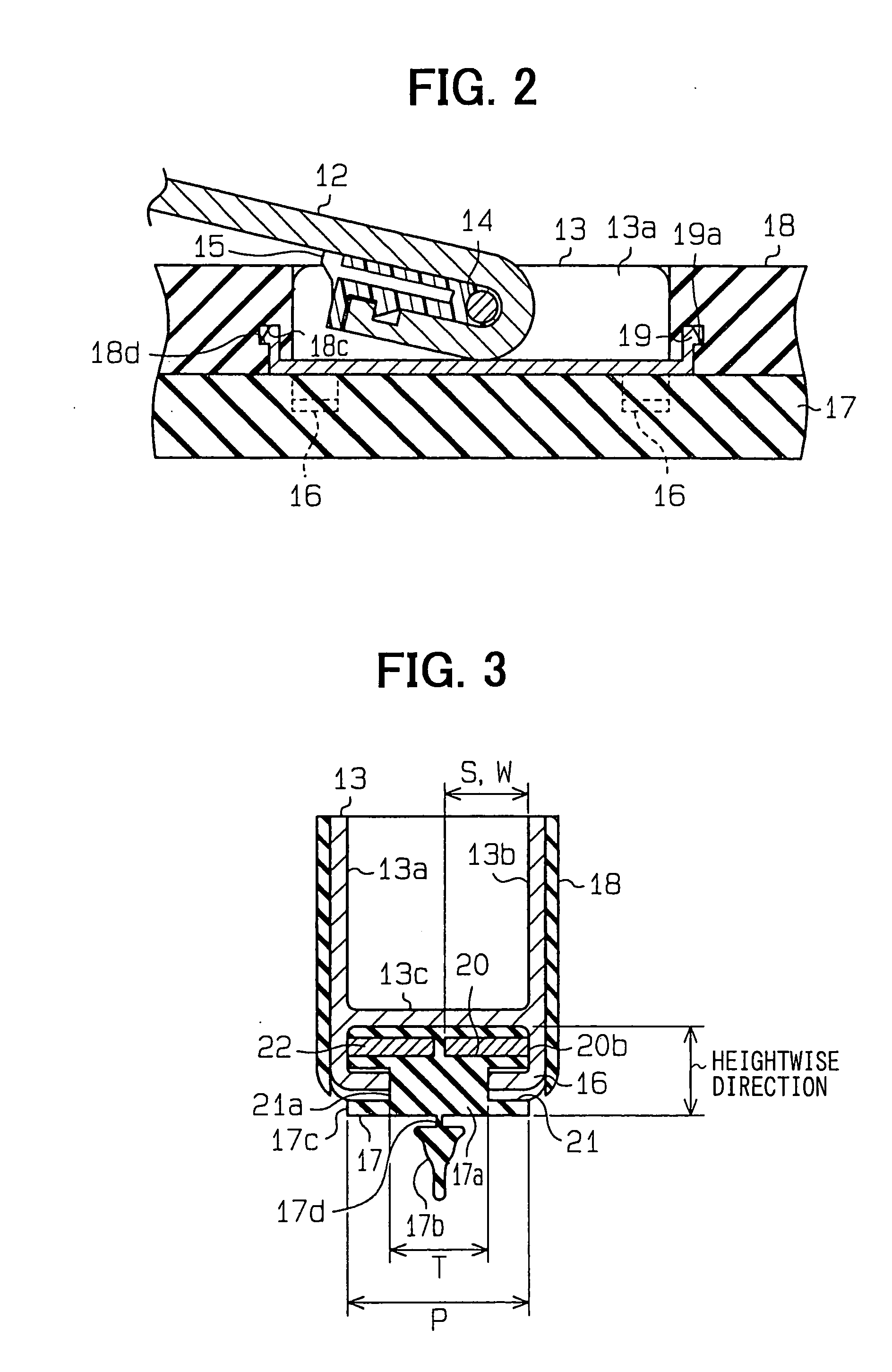
[0032] As shown in FIG. 2, a distal end of the wiper arm 12 is U-shaped, and a holder 13 is connected to the U-shaped distal end of the wiper arm 12. The holder 13 is made of a rigid material (e.g., a metal material or alternatively a rigid resin material) and has a connect...
second embodiment
[0071] A second embodiment of the present invention will be described with reference to FIGS. 8A to 10. In the present embodiment, components similar to those discussed in the first embodiment will be indicated by the same numerals and will not be described further.
[0072] With reference to FIGS. 8A and 8B, a rail 31, which serves as a holding member, is provided to cover the connecting body 17a of the blade rubber 17. The rail 31 extends in the longitudinal direction of the blade rubber 17. The rail 31 is made of a resiliently deformable resin material and can be deformed to coincide with the curved shape of the backing plate 22.
[0073] As shown in FIGS. 8A and 8B, the holder 13 is secured to the longitudinal center of the rail 31. As shown in FIG. 9, the holder 13 is connected to the rain 31 and the blade rubber 17 through the claws 16 of the holder 13. In the area where the claws 16 are formed, the rail 31 covers only a portion (an upper portion in FIG. 9) of the connecting body 17...
third embodiment
[0084] A third embodiment of the present invention will be described with reference to FIG. 11. In the present embodiment, components similar to those discussed in the first embodiment will be indicated by the same numerals and will not be described further.
[0085] With reference to FIG. 11, the blade rubber 17, to which the holder 13 is connected, is made of a rubber material and is elongated in the longitudinal direction of the wiper blade. Furthermore, the blade rubber 17 includes the connecting body 17a and the wiping lip 17b. The connecting body 17a includes the backing grooves 20, the holder grooves 28 and fin support grooves 41. The backing grooves (primary grooves) 20 are provided on the outer lateral surfaces 17c of the connecting body 17a. The holder grooves 28 serve as tertiary grooves. The fin support grooves 41 serve as secondary grooves. With this arrangement, a cross sectional area of the connecting body 17a is necked at three vertical points in FIG. 11.
[0086] The fin ...
PUM
 Abstract
Description
Claims
Application Information
 - R&D
- Intellectual Property
- Life Sciences
- Materials
- Tech Scout
- Unparalleled Data Quality
- Higher Quality Content
- 60% Fewer Hallucinations
Browse by: Latest US Patents, China's latest patents, Technical Efficacy Thesaurus, Application Domain, Technology Topic, Popular Technical Reports.
© 2025 PatSnap. All rights reserved.Legal|Privacy policy|Modern Slavery Act Transparency Statement|Sitemap|About US| Contact US: help@patsnap.com


