Mountable type microwave oven

a microwave oven and wall-mounted technology, which is applied in the field can solve the problems of reducing productivity and complicated manufacture of wall-mounted microwave ovens, and achieve the effect of reducing production costs and ensuring the safety of electrical components

Active Publication Date: 2004-12-30
SAMSUNG ELECTRONICS CO LTD
View PDF5 Cites 12 Cited by
  • Summary
  • Abstract
  • Description
  • Claims
  • Application Information

AI Technical Summary

Benefits of technology

0012] The cooling-ventilation fan may be positioned on an upper surface of the machine room such that air discharged from the cooling-ventilation fan has a sufficient flow rate to efficiently cool the electrical components in the machine room.

Problems solved by technology

However, since the conventional wall-mounted type microwave oven includes an exhaust fan assembly having a pair of exhaust fans, which is provided at a rear-upper portion of oven cabinet to discharge contaminated air generated from cooking appliances installed below the microwave oven, and an additional cooling fan to cool the machine room and to ventilate the cooking chamber, there are problems in that manufacture of the wall-mounted type microwave oven is complicated and productivity is lowered owing to an increased number of components.

Method used


Image

  • Mountable type microwave oven
  • Mountable type microwave oven
  • Mountable type microwave oven

Examples


Embodiment Construction

[0023] Reference will now be made in detail to the present embodiments of the present invention, examples of which are illustrated in the accompanying drawings, wherein like reference numerals refer to like elements throughout. The embodiments are described below to explain the present invention by referring to the figures.

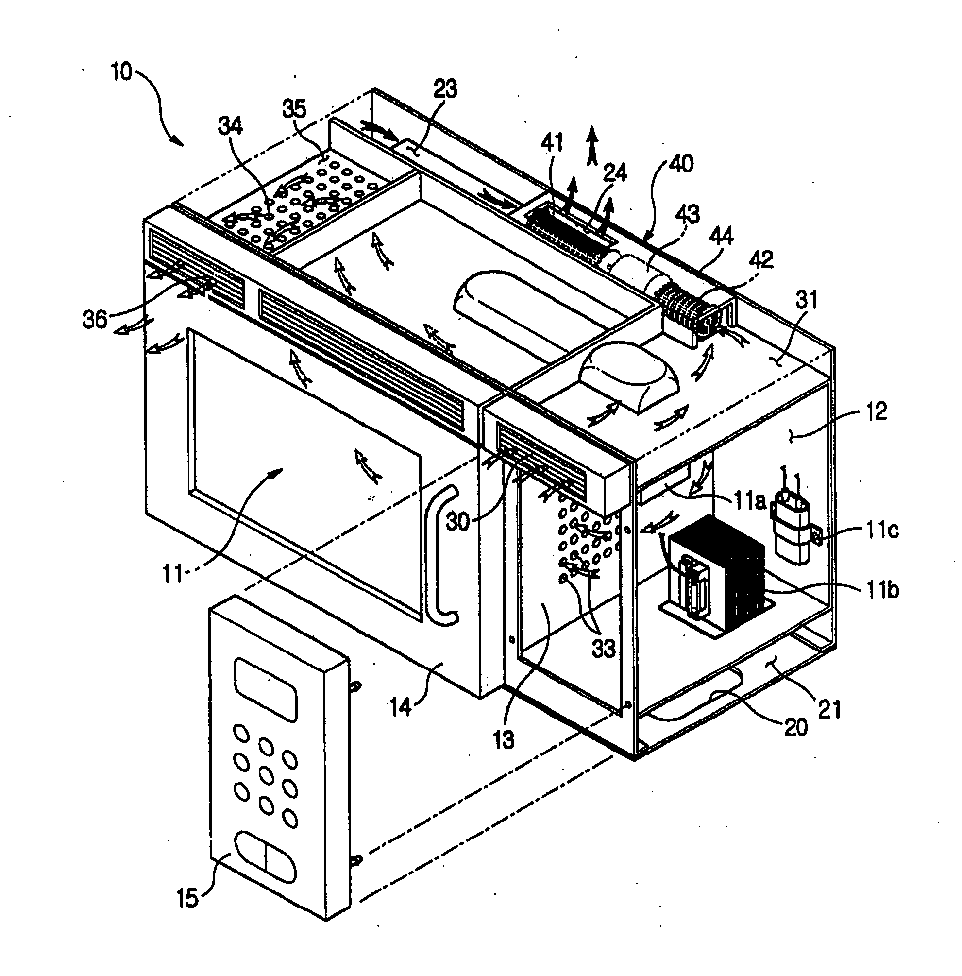
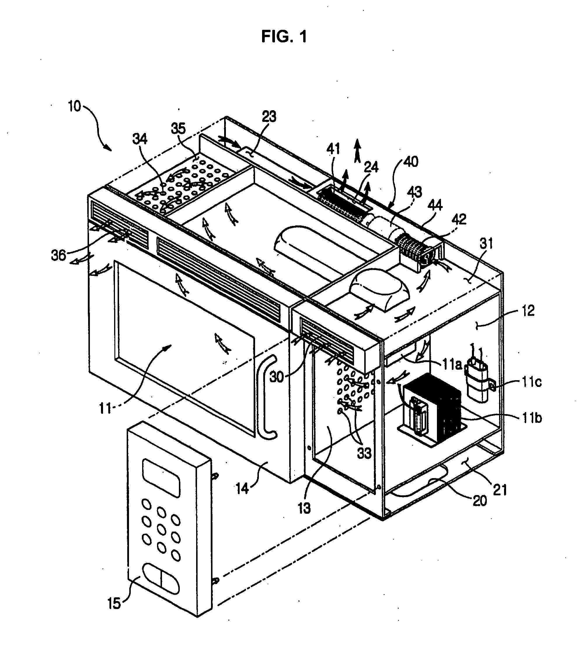
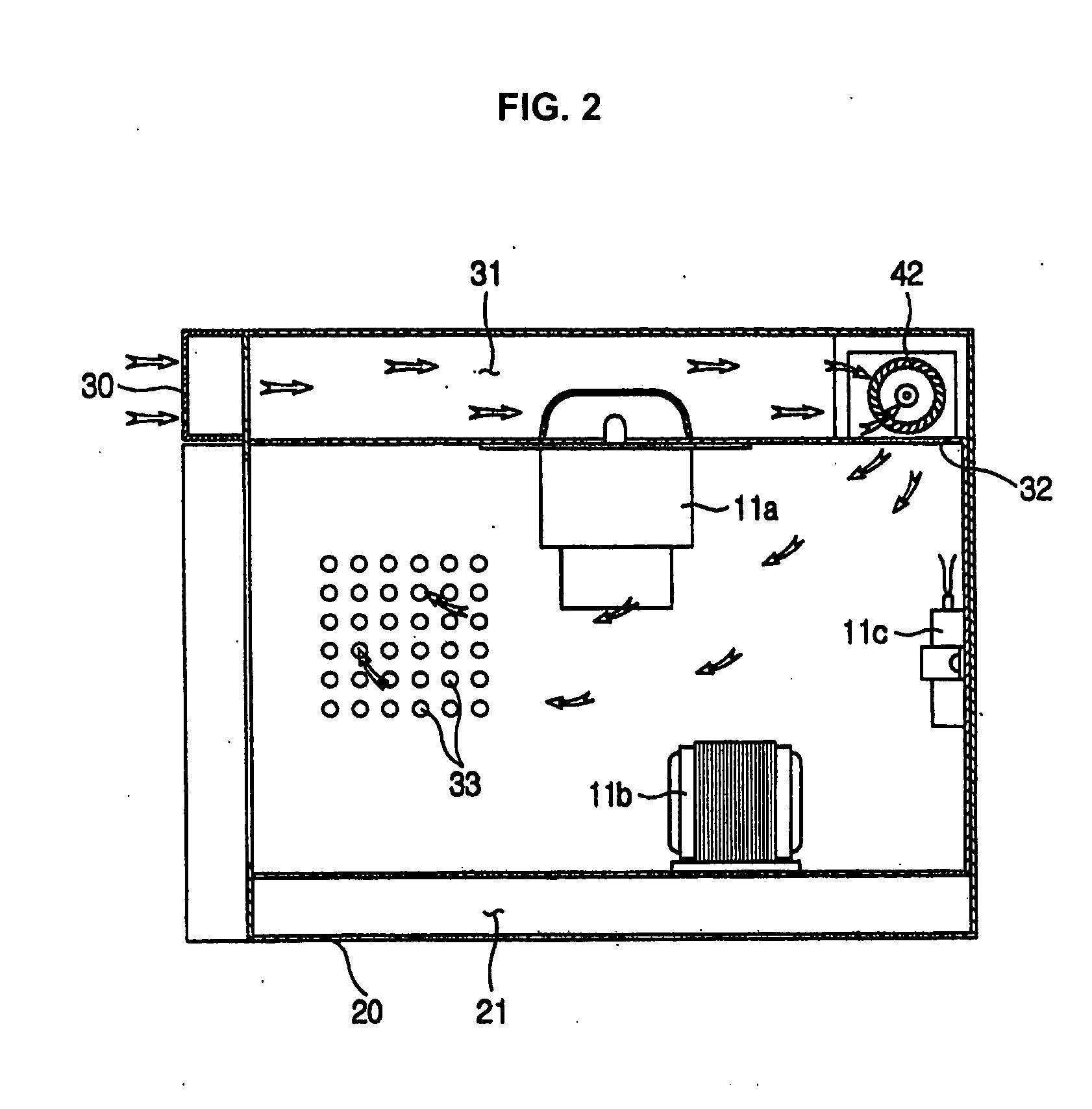
[0024] As shown in FIGS. 1 and 2, a mountable type microwave oven according to an embodiment of the present invention is securely mounted on a wall of a cooking space over cooking appliances such as an oven range (not shown). A rear panel of a cabinet 10 of the microwave oven is securely attached to the wall in the shown embodiment. The wall-mounted type microwave oven is designed to carry out a function of exhausting air contaminated by exhaust gas generated from the oven range disposed below, to the outside, as well as a cooking function. It is to be appreciated that in another aspect of the present invention the microwave oven may be mounted underneath a storag...


PUM


Abstract

A mountable type microwave oven including a blower fan assembly installed at a rear-upper portion of a cabinet to cool a machine room and ventilate a cooking chamber. The microwave oven includes a cabinet mounted on a wall of a cooking space, or under a storage cabinet, and having a cooking chamber to cook food therein and a machine room to house a plurality of electrical components, which are isolated from each other, an exhaust path to exhaust contaminated air generated from a cooking appliance installed below the wall-mounted microwave oven, a cooling-ventilation path to cool the machine room and to ventilate the cooking chamber, and a blower fan assembly including a drive motor having a pair of shafts to generate a rotating force, an exhaust fan joined to one shaft of the drive motor to generate a suction force and a propulsive force to cause the contaminated air to flow along the exhaust path, and a cooling-ventilation fan joined to the other shaft of the drive motor to generate suction and propulsive forces to cause air to flow along the cooling-ventilation path. Since the cooling-ventilation fan performs cooling of the machine room and ventilation of the cooking chamber, there is no need to provide an additional blower fan. Thus, the number of components of the microwave oven is reduced, thereby reducing production costs and improving productivity.

Description

[0001] This application claims the benefit of Korean Application No. 2003-41240, filed Jun. 24, 2003, in the Korean Intellectual Property Office, the disclosure of which is incorporated herein by reference.[0002] 1. Field of the Invention[0003] The present invention relates to a wall-mounted type microwave oven, and more particularly, to a wall-mounted type microwave oven, that includes a blower fan assembly installed at a rear-upper portion of an oven cabinet to cool a machine room as well as to ventilate a cooking chamber.[0004] 2. Description of the Related Art[0005] Generally, a conventional wall-mounted type microwave oven is installed over an oven range in a cooking space, and serves to carry out a function of exhausting air contaminated by exhaust gas generated from the oven range disposed therebelow, to the outside, as well as a cooking function as in a conventional microwave oven.[0006] The wall-mounted type microwave oven includes an oven cabinet forming an appearance, whi...

Claims


Application Information

Patent Timeline
Patent Type & Authority Applications(United States)
IPC IPC(8): H05B6/80F24C15/20
CPCH05B6/642H05B6/6429F24C15/20
Inventor KANG, JEON-HONG
Owner SAMSUNG ELECTRONICS CO LTD
Why Eureka
Try Eureka