Dialysis catheter

a catheter and dialysis technology, applied in the direction of catheters, multi-lumen catheters, coatings, etc., can solve the problems of difficult to ensure an adequate flow rate of blood, the diameter of each of the blood removal holes is inevitably reduced in view of the relationship between space and strength, and the efficiency of blood replacement cannot be considered good, etc., to achieve excellent dialysis efficiency, reduce the number of components, and simplify the structure

Inactive Publication Date: 2013-02-28
TYCO HEALTHCARE GRP LP
View PDF5 Cites 12 Cited by
  • Summary
  • Abstract
  • Description
  • Claims
  • Application Information

AI Technical Summary

Benefits of technology

[0012]According to the invention disclosed in embodiment 1, the side hole is therefore a long hole having a relatively large diameter which extends in the catheter long-axis direction, so the cross-sectional area of the flow path can be increased. Furthermore, when this kind of side hole is used as a blood removal hole, there is less likelihood of suction against the blood vessel wall causing closure. This means that there is good patency and it is possible to ensure an adequate flow rate of blood, and the blood replacement efficiency can be improved. Moreover, when viewed from the first direction, the angle formed by the tip-end opening edge of the side hole and the catheter long-axis direction, and the angle formed by the base-end opening edge of the side hole and the catheter long-axis direction are both small angles. Consequently, the two opening edges of the side hole are unlikely to catch on the blood vessel when the catheter is inserted or withdrawn, so the catheter can be inserted and withdrawn with little resistance. This means that the catheter can be inserted and withdrawn more easily. In addition, when viewed from the first direction, the base-end surface of the closure member is shaped to follow the shape of the tip-end opening surface of the side hole, so it is possible to prevent adhesion and formation of blood clots, without blood accumulating in that region or disturbing the flow of blood.
[0023]As described above in detail, the inventions according to embodiments 1 to 6 make it possible to provide a dialysis catheter which is superior in terms of both ease of insertion / withdrawal and blood replacement efficiency, and which also makes it possible to prevent the accumulation of blood etc., which causes the formation of blood clots and adhesion.

Problems solved by technology

Side-hole type catheters are relatively easy to insert, but the blood removal hole is likely to be sucked against the blood vessel wall, and therefore the patency is poor and it is not possible to ensure an adequate flow rate of blood, which means that the blood replacement efficiency can hardly be considered good.
However, when multiple blood removal holes are to be provided in a conventional side-hole type dialysis catheter, the diameter of each of the blood removal holes is inevitably reduced in view of the relationship between space and strength etc.
However, if this structure is adopted, the blood removal holes may be closed off as they suck against the blood vessel wall, in which case the patency deteriorates and it is difficult to ensure an adequate flow rate of blood.
In addition, depending on the size and shape of the blood removal holes there may also be greater resistance to insertion and withdrawal, something which is contrary to the intended aim.
The base-end side of the closure member extends close to the position on the blood removal lumen where the blood removal hole is formed, but there are problems in that blood accumulates in that region and the flow of blood is disturbed, among other things.

Method used


Image

  • Dialysis catheter
  • Dialysis catheter
  • Dialysis catheter

Examples


Embodiment Construction

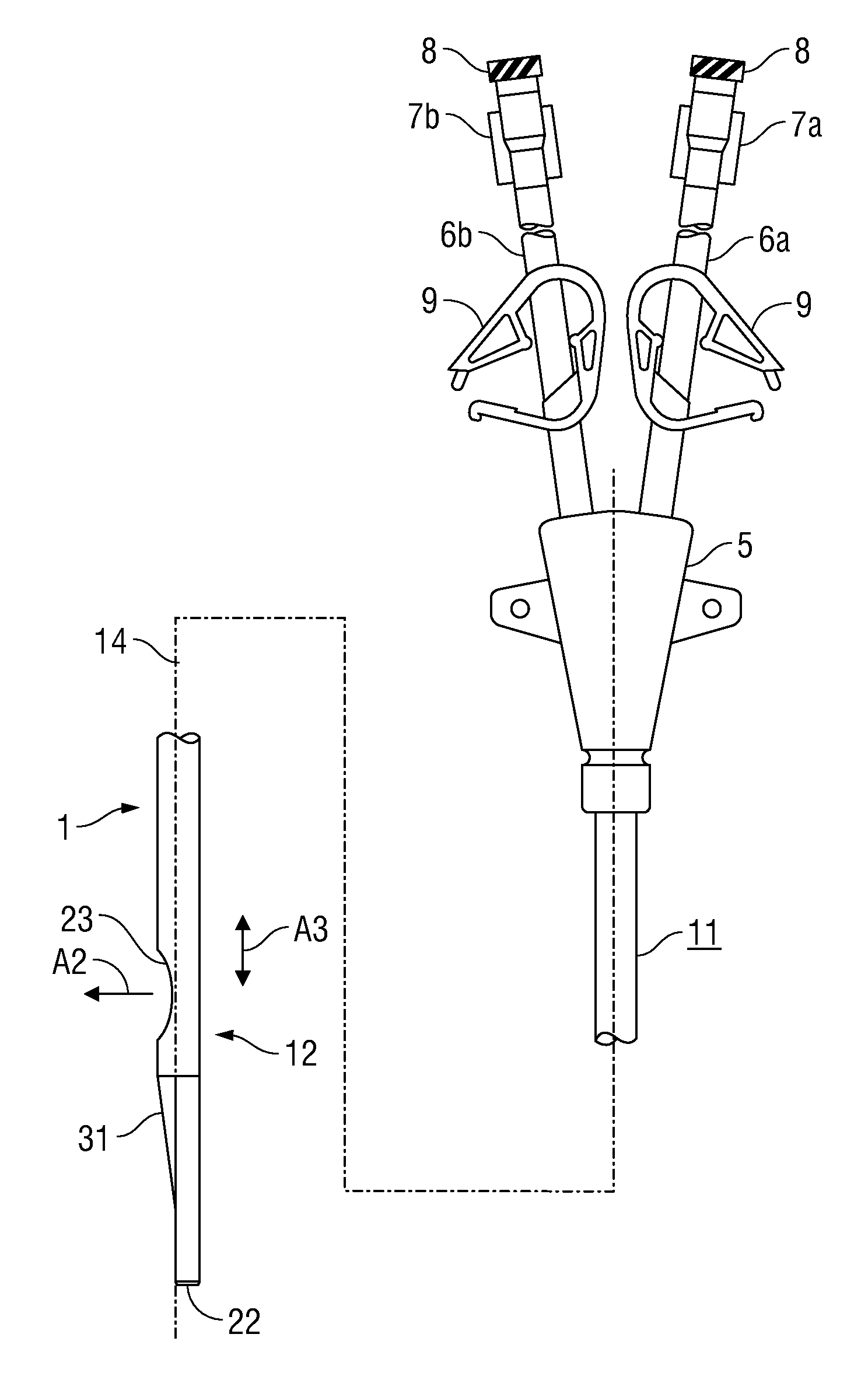
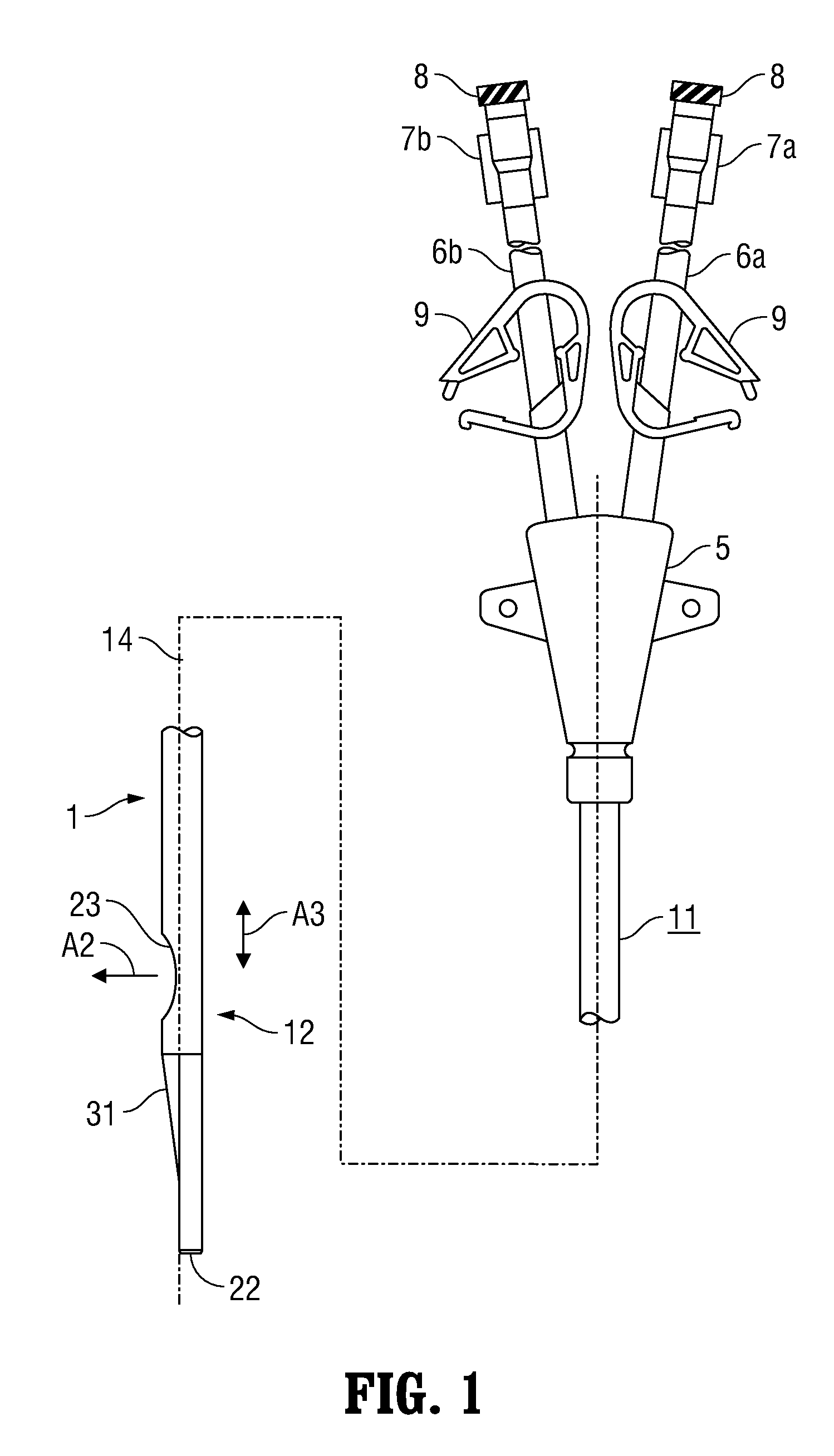
[0040]A dialysis catheter 1 (double-lumen catheter) according to a first embodiment of the present invention will be described in detail below in conjunction with FIGS. 1 to 7.

[0041]As shown in FIG. 1 etc., the dialysis catheter 1 according to this embodiment is provided with a catheter main body (shaft) 11 of circular cross section which is made of a resilient, flexible resin material formed to be elongate. A connecting part 5 comprising two connecting tubes 6a, 6b is joined as a single piece to the base end of the catheter main body 11. The connecting tubes 6a, 6b respectively communicate with the lumens of the catheter main body 11. Luer adapters 7a, 7b to which a dialysis circuit etc. is connected are formed as a single piece at the tip ends of the connecting tubes 6a, 6b. It should be noted that the connecting tubes 6a, 6b and the luer adapters 7a, 7b are formed by separate elements, and they may be fixed to one another by means of bonding or the like.

[0042]A thread 8 is formed...


PUM

PropertyMeasurementUnit
angleaaaaaaaaaa
angle θ1aaaaaaaaaa
angles θ1aaaaaaaaaa

Abstract

A dialysis catheter is disclosed which comprises a catheter main body and a closure member. The catheter main body includes a first lumen which communicates with a tip-end hole and a second lumen which communicates with a side hole. The closure member has a shape in which a tip-end side of the closure member is inclined with a reduced diameter for closing off a tip-end opening. The side hole is a long hole extending in the catheter long-axis direction. The major axis of the side hole is at least 1.5 times the outer diameter of the catheter, and the minor axis is between 0.5 and 0.9 times the outer diameter. A base-end side of the closure member extends to the position of the side hole and seals the tip-end region thereof.

Description

CROSS REFERENCE TO RELATED APPLICATION[0001]This application claims the benefit of and priority to Japanese Patent Application Serial No. 2011-186775 which was filed on Aug. 30, 2011, the entirety of which is incorporated herein by reference.BACKGROUND[0002]1. Technical Field[0003]The present invention relates to a dialysis catheter comprising multiple lumens.[0004]2. Description of Prior Art[0005]Medical catheters are conventionally used in fields of medical care such as surgery, treatment and diagnosis for applications in which liquid is removed from a body cavity and fluid is introduced into a body cavity at the same time. A specific example of this is an application in which blood is removed from a blood vessel and purified blood is once again introduced into the blood vessel in order to perform dialysis using a hemodialysis apparatus. Furthermore, the dialysis catheter used for this kind of application is a well known type of catheter referred to as a double-lumen catheter whic...

Claims


Application Information

Patent Timeline
Patent Type & Authority Applications(United States)
IPC IPC(8): A61M25/14A61M1/14
CPCA61M1/3653A61M25/003A61M25/0045A61M1/3661A61M25/0069A61M25/007A61M2025/0031A61M25/0054A61M1/3659
Inventor MAKINO, MASANORIKANIE, NOBUATSUAKAIKE, YOSHIMI
Owner TYCO HEALTHCARE GRP LP
Why Eureka
Try Eureka