Aeronautical engine with cooling of an electric starting device

a technology of aeronautical engines and electric starting devices, which is applied in the direction of machines/engines, efficient propulsion technologies, mechanical apparatuses, etc., can solve the problems of increasing mass, and achieve the effects of reducing mass, improving reliability, and reducing capacity

Active Publication Date: 2011-12-08
SN DETUDE & DE CONSTR DE MOTEURS DAVIATION S N E C M A
View PDF9 Cites 11 Cited by
  • Summary
  • Abstract
  • Description
  • Claims
  • Application Information

AI Technical Summary

Benefits of technology

[0015]Thus, during the starting phase, the electric pump may contribute to providing a sufficient fuel flow rate to the main fuel feeding circuit. It is then possible to use a high pressure pump of the gear type, but with a lower capacity, or a high pressure pump of the centrifugal type which has a lower mass and more reliability than a gear pump, although it delivers a lower fuel flow at the low starting speed.

Problems solved by technology

But such a solution is expressed by an increase in mass, by the requirement of an additional mechanical link with the AGB and poses a problem at high speed by diverting then a too large flow of fuel.

Method used


Image

  • Aeronautical engine with cooling of an electric starting device
  • Aeronautical engine with cooling of an electric starting device
  • Aeronautical engine with cooling of an electric starting device

Examples


Embodiment Construction

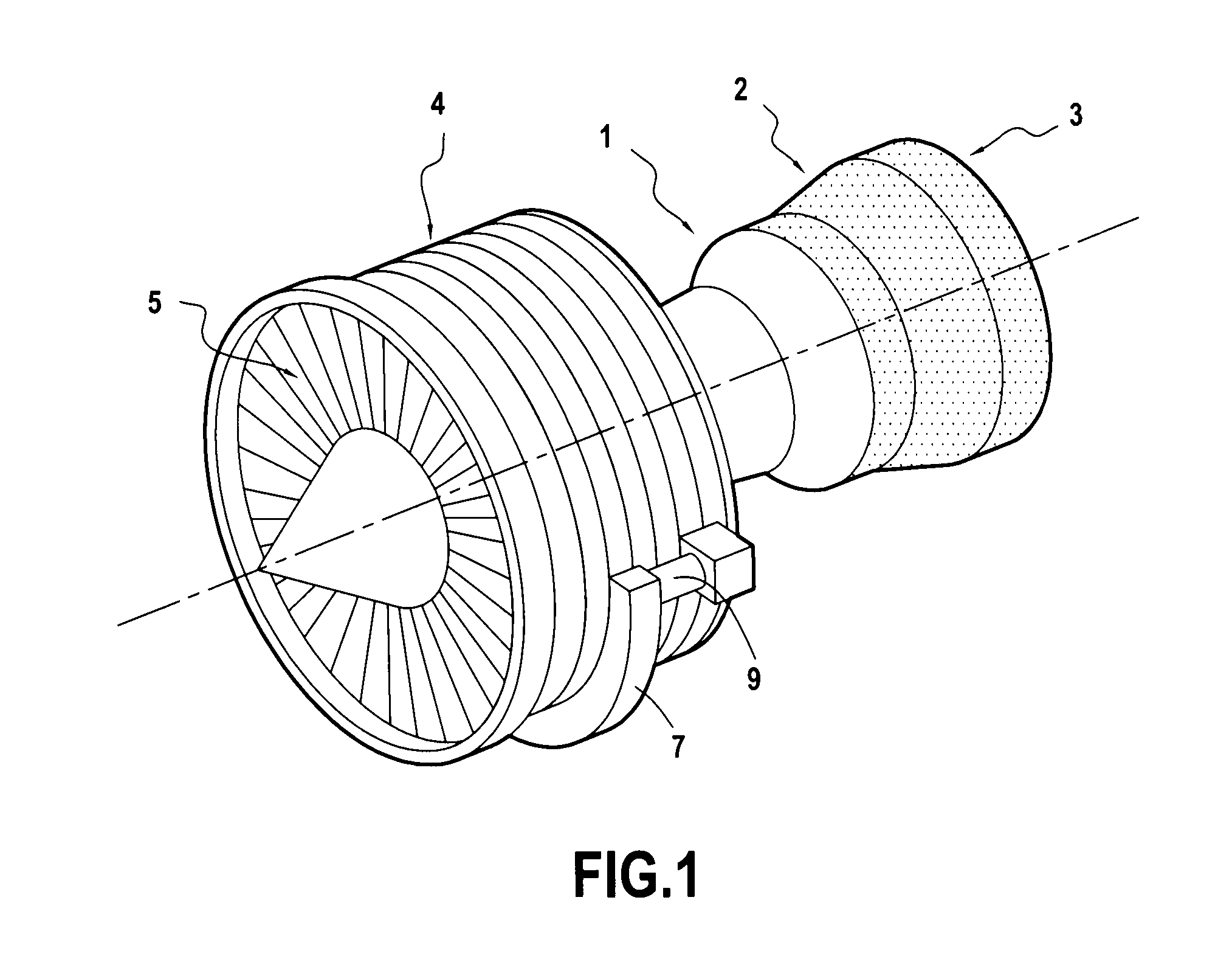
[0021]A field of application of the invention is that of aircraft gas turbine engines, such as the one illustrated very schematically in FIG. 1, the invention being however applicable to other aeronautical engines, notably helicopter turbines, as well as to landborne and marine engines.

[0022]The engine of FIG. 1 comprises a combustion chamber 1, the combustion gases from the latter driving a high pressure turbine 2 and a low pressure turbine 3. The turbine 2 is coupled through a shaft to a high pressure compressor feeding the combustion chamber with pressurized air while the low pressure turbine is coupled through another shaft to a fan 5 at the inlet of the engine.

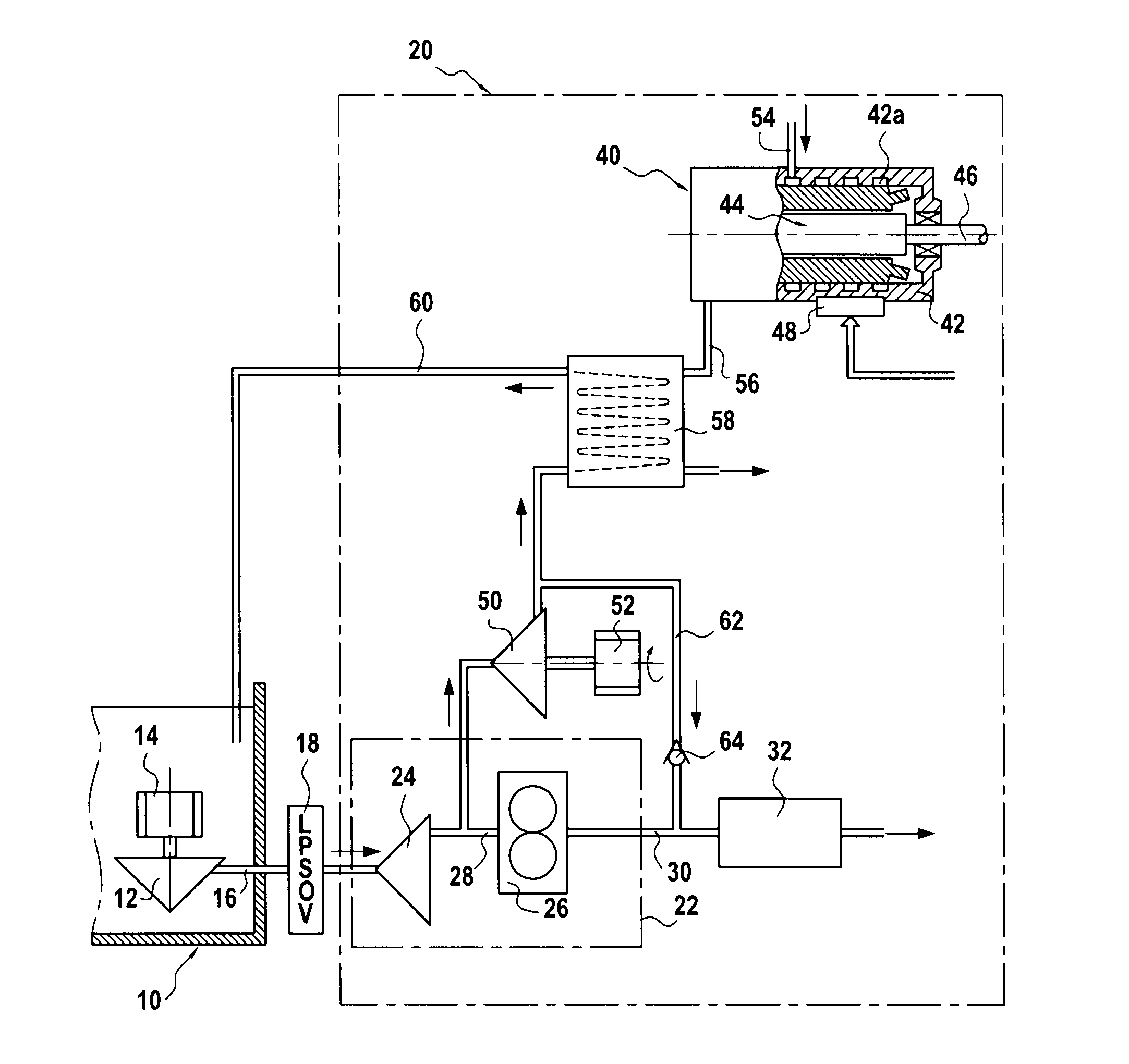
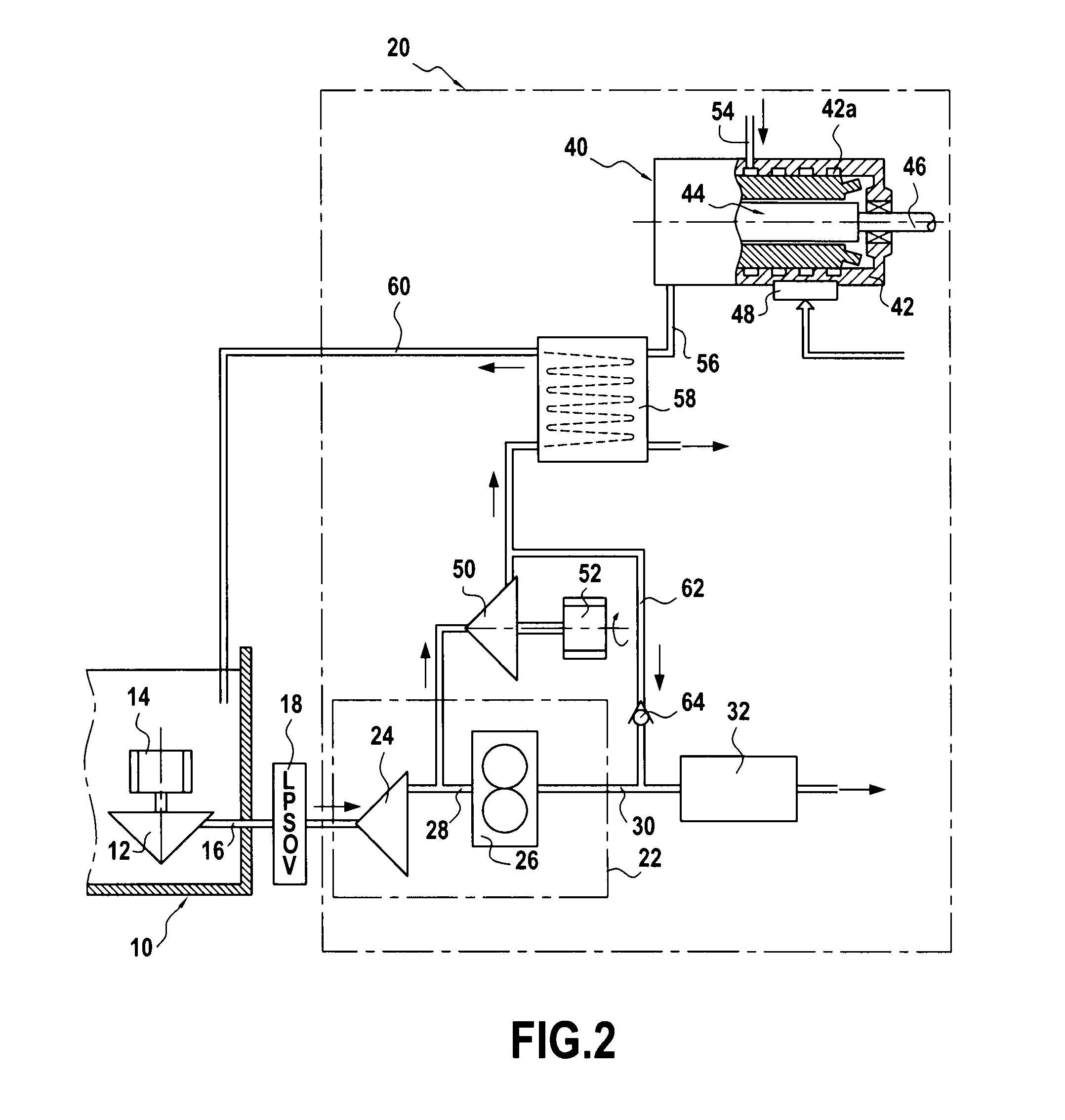
[0023]A transmission box or accessory gear box AGB 7 is connected through a mechanical power take-off 9 to a turbine shaft and comprises an assembly of gear wheels for mechanical coupling with a certain number of accessories. FIG. 2 is a simplified diagram notably showing an engine portion according to an embodiment of th...


PUM


Abstract

An aeronautical engine including a fuel pumping device including a high pressure fuel pump including an inlet connected to a low pressure fuel conduit and an outlet connected to a main circuit for feeding high pressure fuel, an electric device starting the engine, and a device cooling the electric starting device connected to the pumping device to ensure cooling by circulation of fuel. The cooling device is supplied with fuel by a pump that includes an inlet connected to the pumping device, upstream from the high pressure pump, and that is driven by an electric motor independently of the high pressure pump.

Description

BACKGROUND OF THE INVENTION[0001]The invention relates to the cooling of electric devices for starting aeronautical engines.[0002]A particular field of application of the invention is that of aeronautical engines with a gas turbine, in particular turbo-engines.[0003]The starting of an aeronautical engine is conventionally ensured by an electric machine driving a shaft of the engine. The electric machine may be an electric motor or a machine forming a starter / generator (or S / G) operating in a motor mode upon starting and then in a synchronous generator mode.[0004]It is necessary upon starting to remove the calories produced by the electric starting device, i.e. by the actual electric machine and also preferably by the electronic power circuit used for controlling the electric machine, as for example indicated in document EP 1 953 899.[0005]In an aeronautical engine, the fuel is conventionally used as a coolant fluid either directly or by heat exchange with a heat transfer fluid, for ...

Claims


Application Information

Patent Timeline
Patent Type & Authority Applications(United States)
IPC IPC(8): F02C7/268
CPCF02C7/14F02C7/236Y02T50/675Y02T50/671F02C7/275Y02T50/60
Inventor AUROUSSEAU, CHRISTIAN
Owner SN DETUDE & DE CONSTR DE MOTEURS DAVIATION S N E C M A
Why Eureka
Try Eureka