[0009]These and other objects and advantages of this invention will be more completely understood and appreciated by careful study of the following more detailed description of exemplary embodiments of the invention taken in conjunction with the accompanying drawings, in which:
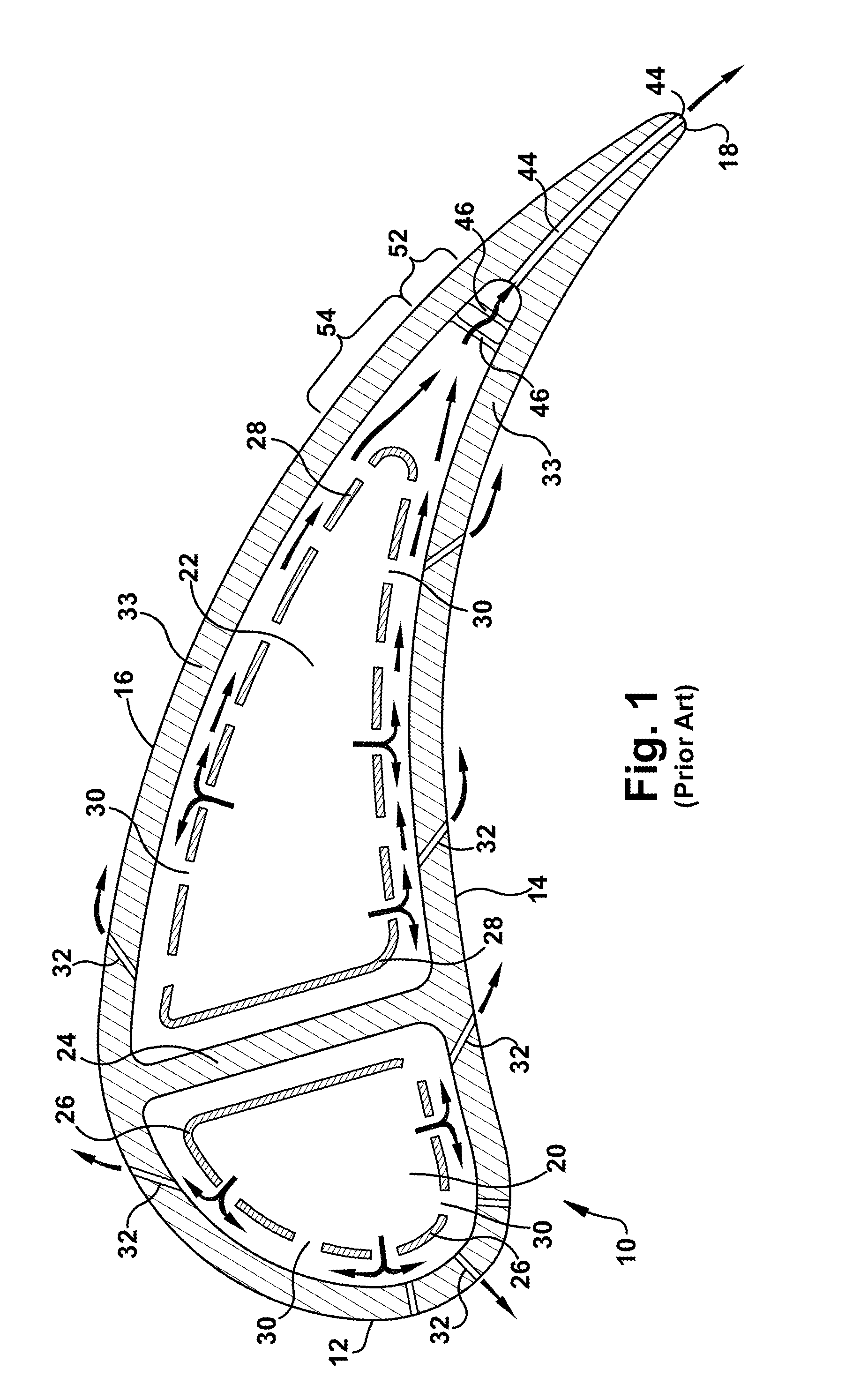
[0010]FIG. 1 is a cross sectional view of a conventional air-cooled airfoil;
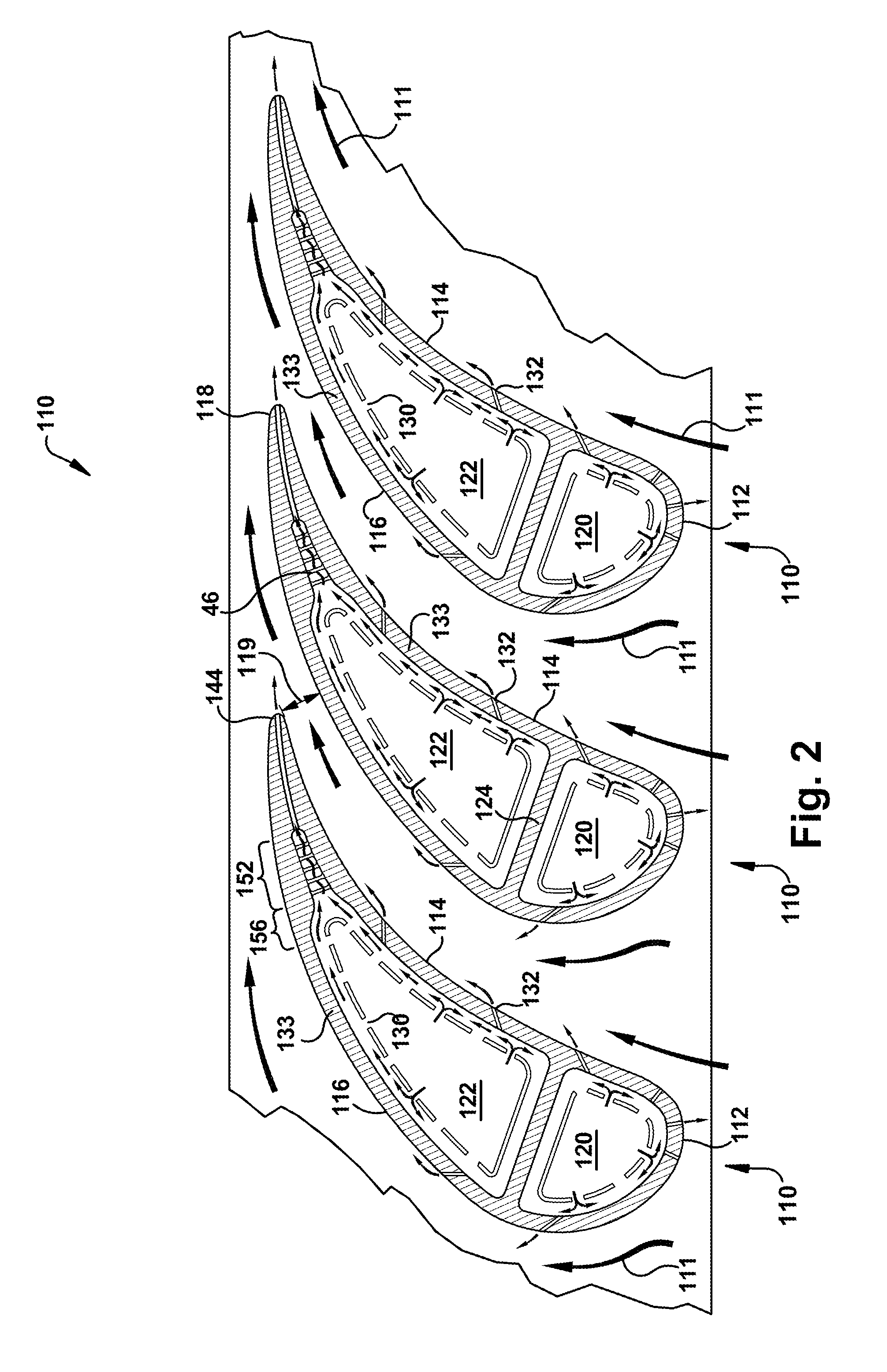
[0011]FIG. 2 is a cross-sectional view of an airfoil illustrating internal cooling circuits according to an exemplary embodiment of the present application; and
[0012]FIG. 3 is an enlarged cross-sectional view of an airfoil illustrating an internal cooling circuit according to an exemplary embodiment of the present application.
[0013]Referring now to the figures, where the various numbers represent like parts throughout the several views, FIG. 1 illustrates a conventional air-cooled airfoil 10. As shown, the airfoil 10 includes an overall airfoil shape, and has a
nose or
leading edge 12, a pressure side or surface 14, a suction side 16 and a trailing edge 18. The airfoil 10 is generally hollow and, often, is divided into two internal chambers 20, 22 by an intermediate partition 24. Each chamber 20, 22 encloses a hollow insert 26, 28 having a configuration generally conforming to the internal contour of the respective chamber but in spaced relation thereto. The inserts 26, 28 contain apertures 30 in preselected locations.
High pressure cooling air from the turbine compressor is directed into the inserts per conventional systems and methods, and is exhausted through such apertures to form jets of air striking the inner walls of the chambers 20, 22 for impingement cooling (as shown by the arrows).
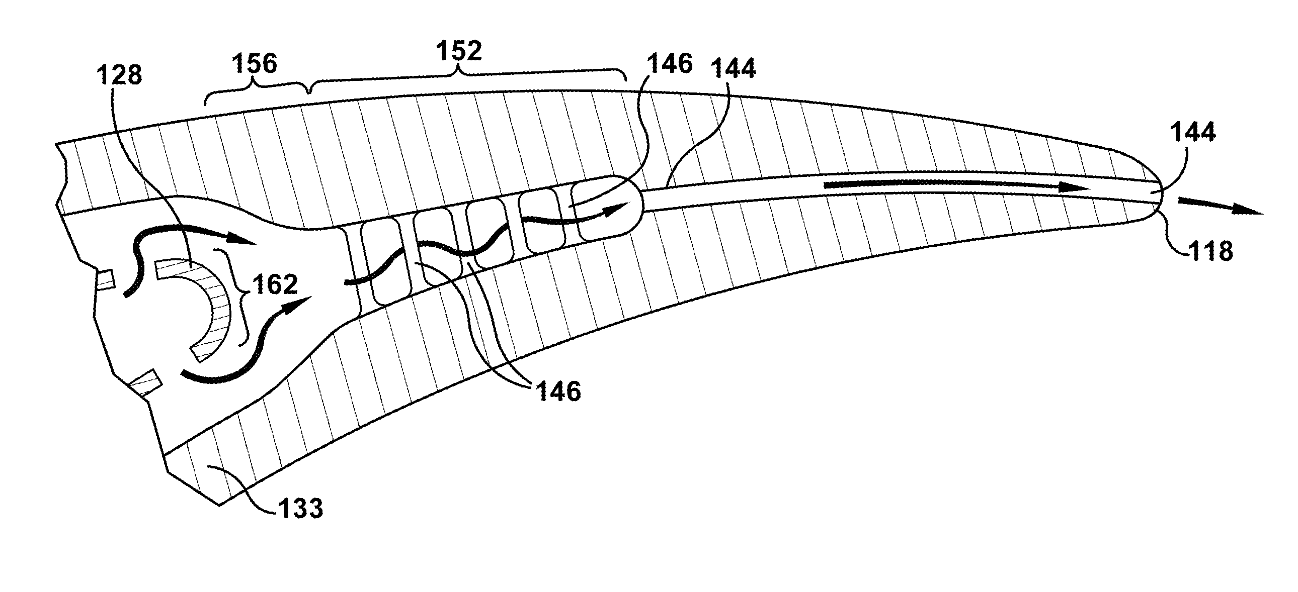
[0027]Third, in embodiments of the present invention, the contoured exit 156 and the downstream entrance to the pin array section 152 are contoured by increasing the walls thickness on both the pressure side 114 and suction side 116 of the airfoil. As a result, the first pin row can be pushed further forward while still not exceeding a pin length that would make
casting the pin troublesome or overly expensive. With pins now generally located in what was the low
heat transfer region 54, the cooling of this area is enhanced, the localized hot spot is reduced, and the need for film cooling flow downstream of the
throat is minimized. In a preferred embodiment, the shape of the contoured exit 156, moving from leading to trailing portions of the contoured exit 156, may generally form a concave curve that transitions to a convex curve, as illustrated. This shape may allow for a smooth transition that also rapidly narrows the thickness of the trailing edge internal chamber 122 such that the first pin 146 of the pin array section 152 may be pushed forward as much as possible. In addition, this configuration of the contoured exit 156 enhances cooling just downstream of the trailing edge insert 128 as the airfoil walls converge the channel area to maximize cooling
air velocity and increase
heat transfer coefficients through this channel.
[0021]As described above, in conventional air-cooled airfoils, the general area that coincides with the location of the contoured exit 156 and part of the pin array section 152 is generally a difficult area to cool. That is, the region in between the end of the trailing edge insert 128 and what was the beginning of the pin array 152 in conventional designs is generally an area of low
heat transfer coefficients. This is so because there is little or no flow impingement and no heat transfer augmentation features, such as an array of pins, in this area. Therefore, this region is prone to higher
metal temperatures, which may decrease the part life of an airfoil. In addition, as described above, releasing air from film cooling apertures 132 that are located downstream of the
throat 119 has a significant negative effect to the aerodynamic efficiency of the part. As such, generally, releasing cooling air downstream of the throat 119 is avoided or minimized, which adds to the difficulty of keeping this area cool.
[0027]Third, in embodiments of the present invention, the contoured exit 156 and the downstream entrance to the pin array section 152 are contoured by increasing the walls thickness on both the pressure side 114 and suction side 116 of the airfoil. As a result, the first pin row can be pushed further forward while still not exceeding a pin length that would make
casting the pin troublesome or overly expensive. With pins now generally located in what was the low heat transfer region 54, the cooling of this area is enhanced, the localized hot spot is reduced, and the need for film cooling flow downstream of the throat is minimized. In a preferred embodiment, the shape of the contoured exit 156, moving from leading to trailing portions of the contoured exit 156, may generally form a concave curve that transitions to a convex curve, as illustrated. This shape may allow for a smooth transition that also rapidly narrows the thickness of the trailing edge internal chamber 122 such that the first pin 146 of the pin array section 152 may be pushed forward as much as possible. In addition, this configuration of the contoured exit 156 enhances cooling just downstream of the trailing edge insert 128 as the airfoil walls converge the channel area to maximize cooling
air velocity and increase heat transfer coefficients through this channel.
[0022]In the present invention, several parameters relating to the design of this area of the airfoil 110, i.e., the area that roughly corresponds to the low heat transfer region of the airfoil 110, are modified and optimized such that the extent of the low heat transfer area is minimized and / or cooling of this area is enhanced. Accordingly, a design pursuant to an embodiment of the present invention minimizes the region of low heat transfer by reducing the
axial distance between the end of the trailing edge insert 128 and the entrance to the pin array section 152. To minimize this distance, as described in more detail below, several parameters were modified.
[0027]Third, in embodiments of the present invention, the contoured exit 156 and the downstream entrance to the pin array section 152 are contoured by increasing the walls thickness on both the pressure side 114 and suction side 116 of the airfoil. As a result, the first pin row can be pushed further forward while still not exceeding a pin length that would make casting the pin troublesome or overly expensive. With pins now generally located in what was the low heat transfer region 54, the cooling of this area is enhanced, the localized hot spot is reduced, and the need for film cooling flow downstream of the throat is minimized. In a preferred embodiment, the shape of the contoured exit 156, moving from leading to trailing portions of the contoured exit 156, may generally form a concave curve that transitions to a convex curve, as illustrated. This shape may allow for a smooth transition that also rapidly narrows the thickness of the trailing edge internal chamber 122 such that the first pin 146 of the pin array section 152 may be pushed forward as much as possible. In addition, this configuration of the contoured exit 156 enhances cooling just downstream of the trailing edge insert 128 as the airfoil walls converge the channel area to maximize cooling air velocity and increase heat transfer coefficients through this channel.
[0027]Third, in embodiments of the present invention, the contoured exit 156 and the downstream entrance to the pin array section 152 are contoured by increasing the walls thickness on both the pressure side 114 and suction side 116 of the airfoil. As a result, the first pin row can be pushed further forward while still not exceeding a pin length that would make casting the pin troublesome or overly expensive. With pins now generally located in what was the low heat transfer region 54, the cooling of this area is enhanced, the localized hot spot is reduced, and the need for film cooling flow downstream of the throat is minimized. In a preferred embodiment, the shape of the contoured exit 156, moving from leading to trailing portions of the contoured exit 156, may generally form a concave curve that transitions to a convex curve, as illustrated. This shape may allow for a smooth transition that also rapidly narrows the thickness of the trailing edge internal chamber 122 such that the first pin 146 of the pin array section 152 may be pushed forward as much as possible. In addition, this configuration of the contoured exit 156 enhances cooling just downstream of the trailing edge insert 128 as the airfoil walls converge the channel area to maximize cooling air velocity and increase heat transfer coefficients through this channel.
[0021]As described above, in conventional air-cooled airfoils, the general area that coincides with the location of the contoured exit 156 and part of the pin array section 152 is generally a difficult area to cool. That is, the region in between the end of the trailing edge insert 128 and what was the beginning of the pin array 152 in conventional designs is generally an area of low heat transfer coefficients. This is so because there is little or no flow impingement and no heat transfer augmentation features, such as an array of pins, in this area. Therefore, this region is prone to higher
metal temperatures, which may decrease the part life of an airfoil. In addition, as described above, releasing air from film cooling apertures 132 that are located downstream of the throat 119 has a significant negative effect to the aerodynamic efficiency of the part. As such, generally, releasing cooling air downstream of the throat 119 is avoided or minimized, which adds to the difficulty of keeping this area cool.
[0022]In the present invention, several parameters relating to the design of this area of the airfoil 110, i.e., the area that roughly corresponds to the low heat transfer region of the airfoil 110, are modified and optimized such that the extent of the low heat transfer area is minimized and / or cooling of this area is enhanced. Accordingly, a design pursuant to an embodiment of the present invention minimizes the region of low heat transfer by reducing the
axial distance between the end of the trailing edge insert 128 and the entrance to the pin array section 152. To minimize this distance, as described in more detail below, several parameters were modified.
[0023]First, the edge of the trailing edge insert 128 is designed such that it extends toward the pin array section 152 as much as possible while also maintaining the insertability of the trailing edge insert 128. As one of ordinary skill in the art will appreciate, the trailing edge insert 128 generally is not extended back to the extreme trailing
edge region of the trailing edge internal chamber 122 because of insertability issues. This issue is common in many airfoils because of the narrowness of the airfoil in the trailing
edge region and the highly 3-dimensional trailing edge airfoil shape. That is, because the three-dimensional shape of the insert 128 and the varying
axial length at different radial heights, the insert 128 cannot be made to extend all the way to the rear of the trailing edge internal chamber 122, i.e., an area of greater
axial length on the insert 128 would be blocked by an area of lesser
axial length of the chamber 122. However, it has been found that insertability may be maintained while also pushing the trailing edge back further toward the pin array section 152. In the present design, the insert is configured to minimize the gap between the trailing edge of the insert 128 and the beginning of the pin array section 152 while maintaining insertability. Put another way, the insert 128 is configured to extend as far rearward as possible while maintaining insertability.
[0024]In addition, the trailing edge 162 of the insert 128 has a minimum curvature that limits how small the trailing edge 162 can be. The minimum curvature is a function of the material from which the insert is made and, generally, limits the sharpness of the curve that may be made at the trailing edge 162 given a desired level of insert 128 durability. For some conventional materials, the minimum curvature is approximately a
radius that is equal to twice the wall thickness. Generally, there also is minimum outer wall thickness 133. The minimum outer wall thickness is determined given the casting capabilities, a desired level of outer wall 133 durability, including
impact resistance, and the material used. As one of ordinary skill in the art will appreciate, there also is a minimum trailing edge passage thickness. As used herein, a minimum trailing edge passage thickness is the minimum clearance between the insert 128 and the outer wall 133 along the trailing edge of the trailing edge internal chamber 122.
[0025]The minimum trailing edge passage thickness generally is determined by the desired level of flow through the hollow passages of the airfoil 110. That is, the trailing edge passage has to a minimum thickness to allow an adequate flow rate for cooling the airfoil 110. More particularly, the minimum thickness of the trailing edge passage is a thickness that allows a minimum level of cooling air to flow through the airfoil, i.e., enough passage room to allow a desired level of flow to reach the trailing edges of the airfoil such that the airfoil is cooled adequately. As a result, it will be appreciated that given the decreasing thickness of the airfoil 110 of the trailing edge 118, there will generally be a maximum distance the insert may be pushed toward the trailing edge 118 of the airfoil 110 that is dictated by the minimum curvature of the insert 128, the minimum outer wall thickness 133, and the minimum clearance between the insert 128 and the outer wall 133. Accordingly, once these minimum distances require that the airfoil 110 be thicker than the actual airfoil design dimensions, the insert 128 has been pushed too far toward the trailing edge 118.
[0026]Second, the first pin row of the pin array section 152 is configured so that it is positioned as far forward as possible. Generally, due to manufacturing limitations, the length of a pin 146 is restricted. That is, pins 146 that exceed a certain length are not castable and, thus, substantially impossible or very expensive to manufacture. Generally, this maximum pin length is determined by the casting capabilities given the pin
diameter that provides a desired level of heat transfer through the pin array section 152. More particularly, it will be appreciated that maximizing the heat transfer through the pin array will drive the design toward thinner pins. Because of casting limitations, the pin
diameter that delivers sufficient or desired heat transfer through this area will have a maximum length. Given this maximum pin length, the pins 146 are pushed as far forward as possible.
[0027]Third, in embodiments of the present invention, the contoured exit 156 and the downstream entrance to the pin array section 152 are contoured by increasing the walls thickness on both the pressure side 114 and suction side 116 of the airfoil. As a result, the first pin row can be pushed further forward while still not exceeding a pin length that would make casting the pin troublesome or overly expensive. With pins now generally located in what was the low heat transfer region 54, the cooling of this area is enhanced, the localized hot spot is reduced, and the need for film cooling flow downstream of the throat is minimized. In a preferred embodiment, the shape of the contoured exit 156, moving from leading to trailing portions of the contoured exit 156, may generally form a concave curve that transitions to a convex curve, as illustrated. This shape may allow for a smooth transition that also rapidly narrows the thickness of the trailing edge internal chamber 122 such that the first pin 146 of the pin array section 152 may be pushed forward as much as possible. In addition, this configuration of the contoured exit 156 enhances cooling just downstream of the trailing edge insert 128 as the airfoil walls converge the channel area to maximize cooling air velocity and increase heat transfer coefficients through this channel.
[0028]As a result, by minimizing the axial distance between the trailing edge insert 28 and the pin array section 52 and by
contouring the entrance to the pin array section 52 as described, localized hot spots that develop in conventional designs may be substantially eliminated. This result decreases the need for film cooling downstream of the throat 119 and decreases the amount of cooling air needed to cool the airfoil during operation, both of which increase the efficiency of the turbine engine. In some embodiments, the present invention may be used in relation to a
stator blade, and, in particular, as a
stator blade that is used in the turbine section of a gas turbine engine. This is exemplary, as embodiments of the present invention may also be used in rotor blades. Further, in some of cases, the present invention may be configured for use in a first stage stator blade of the turbine section of a gas turbine engine. In some such embodiments, the gas turbine engine may be a 7FA+e turbine engine manufactured by The General Electric Company of Schenectady, N.Y. Again, the optimized trailing edge cooling circuit according to embodiments of the present invention allows film cooling flow introduced downstream of the
nozzle throat to be minimized or eliminated, which decreases aerodynamic mixing losses.
[0028]As a result, by minimizing the axial distance between the trailing edge insert 28 and the pin array section 52 and by
contouring the entrance to the pin array section 52 as described, localized hot spots that develop in conventional designs may be substantially eliminated. This result decreases the need for film cooling downstream of the throat 119 and decreases the amount of cooling air needed to cool the airfoil during operation, both of which increase the efficiency of the turbine engine. In some embodiments, the present invention may be used in relation to a stator blade, and, in particular, as a stator blade that is used in the turbine section of a gas turbine engine. This is exemplary, as embodiments of the present invention may also be used in rotor blades. Further, in some of cases, the present invention may be configured for use in a first stage stator blade of the turbine section of a gas turbine engine. In some such embodiments, the gas turbine engine may be a 7FA+e turbine engine manufactured by The General Electric Company of Schenectady, N.Y. Again, the optimized trailing edge cooling circuit according to embodiments of the present invention allows film cooling flow introduced downstream of the
nozzle throat to be minimized or eliminated, which decreases aerodynamic mixing losses.

