Electromagnetic flow sensor

a technology of electromagnetic flow and sensor, which is applied in the direction of volume/mass flow measurement, measurement devices, instruments, etc., can solve the problem that the spread of magnetic field in the axial direction may no longer be negligibl

Inactive Publication Date: 2005-01-06
ENDRESS HAUSER FLOWTEC AG
View PDF6 Cites 25 Cited by
  • Summary
  • Abstract
  • Description
  • Claims
  • Application Information

AI Technical Summary

Benefits of technology

[0023] As the magnetic field is effectively limited in the axial direction, the flow sensor according to the invention can be fitted

Problems solved by technology

In addition it turned out that at great nominal diameters, where the ratio of nominal diameter to flow-tube length is generally

Method used


Image

  • Electromagnetic flow sensor
  • Electromagnetic flow sensor
  • Electromagnetic flow sensor

Examples


Embodiment Construction

[0030] While the invention is susceptible to various modifications and alternative forms, exemplary embodiments thereof have been shown by way of example in the drawings and will herein be described in detail. It should be understood, however, that there is no intent to limit the invention to the the particular forms diclosed, but on the contrary, the intention is to cover all modifications, equivalents, and alternatives falling within the spirit and scope of the invention as defined by the intended claims.

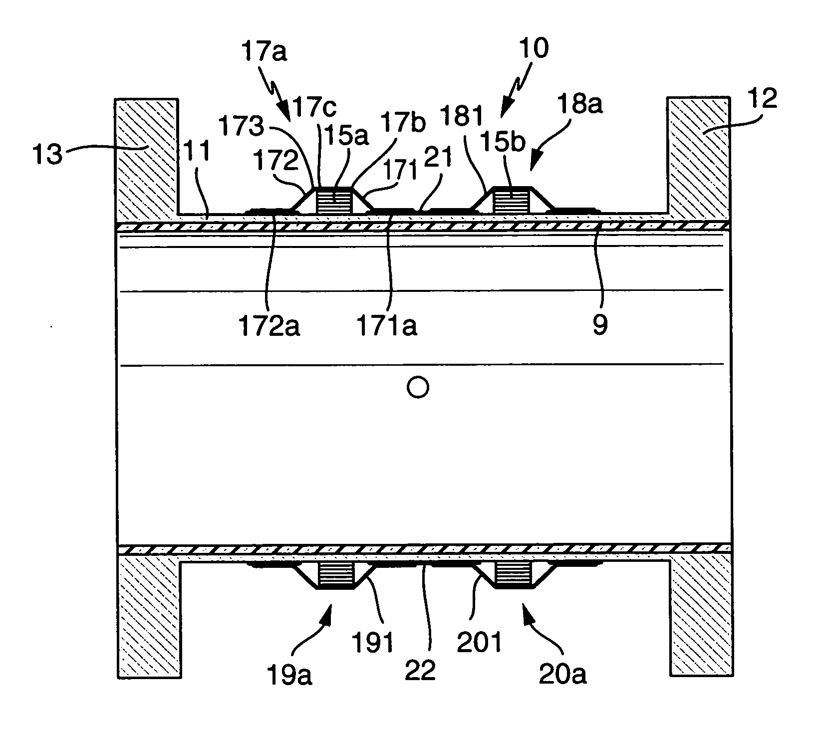
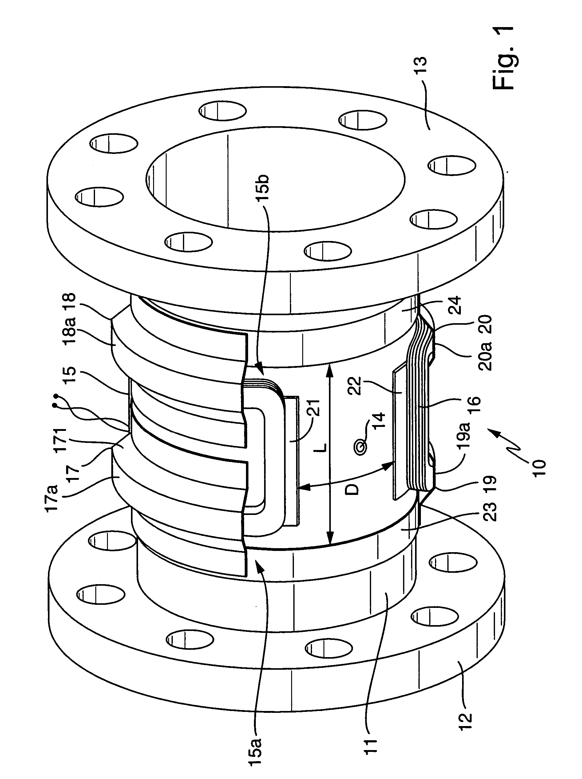
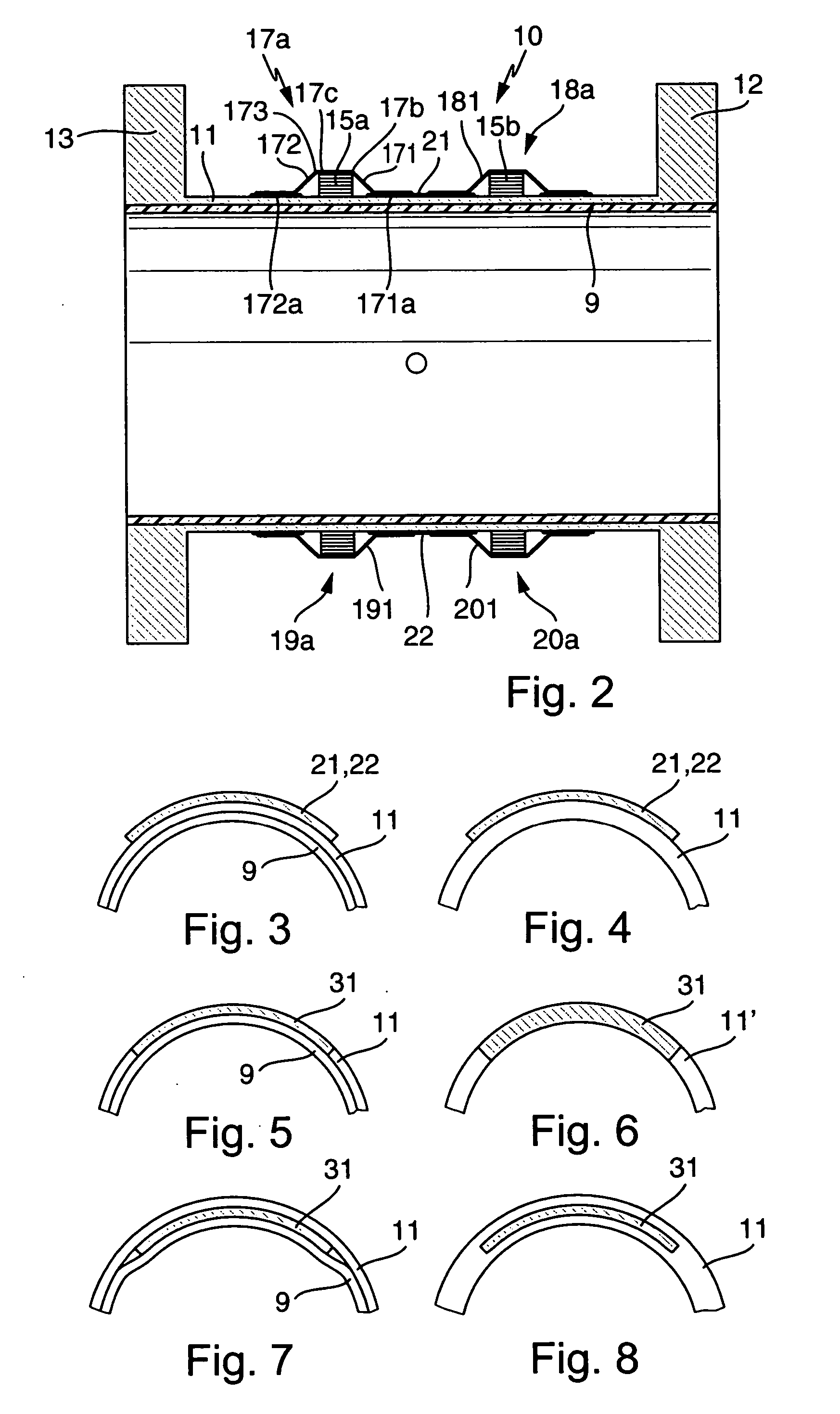
[0031] The electromagnetic flow sensor 10 shown schematically in FIGS. 1 and 2 is particularly suited for measuring an electrically conductive fluid flowing in a pipe (not shown) having a nominal diameter in the range between 200 and 700 mm, particularly between 350 and 600 mm. To conduct the fluid, the flow sensor has a flow tube 11 designed to be inserted into the pipe. Flow tube 11 may be made of nonferromagnetic metal, such as stainless steel, of a suitable ceramic, such as a...


PUM


Abstract

The flow sensor serves to measure an electrically conductive fluid flowing in a pipe. It comprises a flow tube designed to be inserted into the pipe for conducting the fluid, the flow tube being electrically nonconductive at least on a fluid-contacting inner side, an electrode arrangement consisting of at least two measuring electrodes disposed on the flow tube for picking up a voltage induced in the fluid, and a magnetic field system likewise disposed on the flow tube. The magnetic field system comprises at least two saddle-shaped field coils for producing a magnetic field cutting the fluid during operation of the flow sensor, a respective ferromagnetic pole piece for each of the two field coils, as well as at least one ferromagnetic return path extending around the flow tube upstream of the two field coils and at least one ferromagnetic return path extending around the flow tube downstream of the two field coils for directing the magnetic field around the flow tube. The pole pieces are magnetically coupled to the return paths by means of ferromagnetic coupling elements. Each of the, preferably identically shaped, coupling elements has at least one essentially trough-shaped cover segment which receives a first winding section of the respective associated field coil, lying essentially on a first periphery of the flow tube, or a second winding section of the associated field coil, lying essentially on a second periphery of the flow tube.

Description

FIELD OF THE INVENTION [0001] This invention relates to an electromagnetic flow sensor comprising a flow tube, through which flows an electrically conductive fluid to be measured, and saddle coils serving to produce a magnetic field cutting the fluid. BACKGROUND OF THE INVENTION [0002] For the purposes of the description of the invention, “flow sensor” means the essentially mechanical portion of an electromagnetic flowmeter without the coil-current-generating circuit. Such electromagnetic flow sensors, as is well known, use Faraday's law of induction to produce a measurement voltage. [0003] In DE-A 20 40 682, U.S. Pat. No. 4,641,537, U.S. Pat. No. 4,774,844, or WO-A 91 / 11731, different implementations of electromagnetic flow sensors are described, which serve to measure an electrically conductive fluid flowing in a pipe. The flow sensors shown each comprise: [0004] a flow tube designed to be installed in the pipe for conducting the fluid, the flow tube being electrically nonconducti...

Claims


Application Information

Patent Timeline
IPC IPC(8): G01F1/58
CPCG01F1/586
Inventor ZINGG, THOMAS
Owner ENDRESS HAUSER FLOWTEC AG
Why Eureka
Try Eureka