Locking bone plate

a bone plate and locking technology, applied in the field of bone plates, can solve the problems of reducing surgical flexibility, requiring more operating room time, and adding complexity to the procedure, and achieve the effect of greater flexibility of choi

Active Publication Date: 2005-01-20
VIANT AS&O HLDG LLC +1
View PDF90 Cites 178 Cited by
  • Summary
  • Abstract
  • Description
  • Claims
  • Application Information

AI Technical Summary

Benefits of technology

[0019] A bone plate(s) of complex form is provided, particularly suited to tibial plateau-leveling osteotomy and a distal femoral osteotomy. The bone plate has a main longitudinal axis, a bone-contacting bottom side (not shown) and a top side with at least two sets of overlapping holes which communicate through the plate from the top to the bottom side. The sets of overlapping holes define threaded apertures having multifaceted surfaces. When applied to a bone, two sets of such overlapping ...

Problems solved by technology

Although an improvement over the inserts noted above, the locking positions are pre-defined, and only available in limited locations, which also reduce surgical flexibility.
This is not desirable because this requires more operating room time and adds complexity to the procedure.
Further, the inserts must be added in the specific location before the plate is fixed to the bone and cannot be subsequently inserted.
This limits the choice of placement during surgery if the need arises.
Friction locks are not reliable and come lose more easily than threaded locked holes.
The resul...

Method used


Image

  • Locking bone plate
  • Locking bone plate
  • Locking bone plate

Examples


embodiment 130

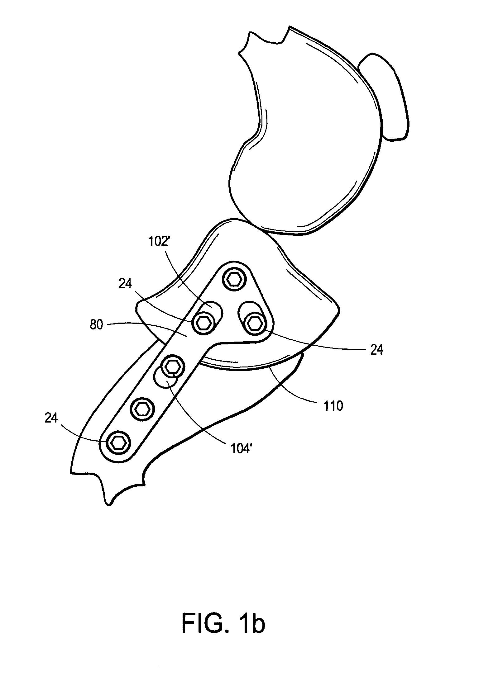
[0036] Referring now to FIG. 2, an alternate embodiment 130 of the invention for this particular application shows typical modifications, such as longer chamfer surfaces 102′ and 104′ in the apertures 84′ and 94′ on either side of the osteotomy site. An elongated slot 86′ in the flat, triangular head 82′ includes a large underside chamfer (not shown) which permits greater bone screw angulation.

embodiment 140

[0037] Referring now to FIG. 3, a second alternate embodiment 140 of the invention for this particular application shows other possible orientations of the apertures. For example, apertures 84″ are oriented off axis in order to suit special cases.

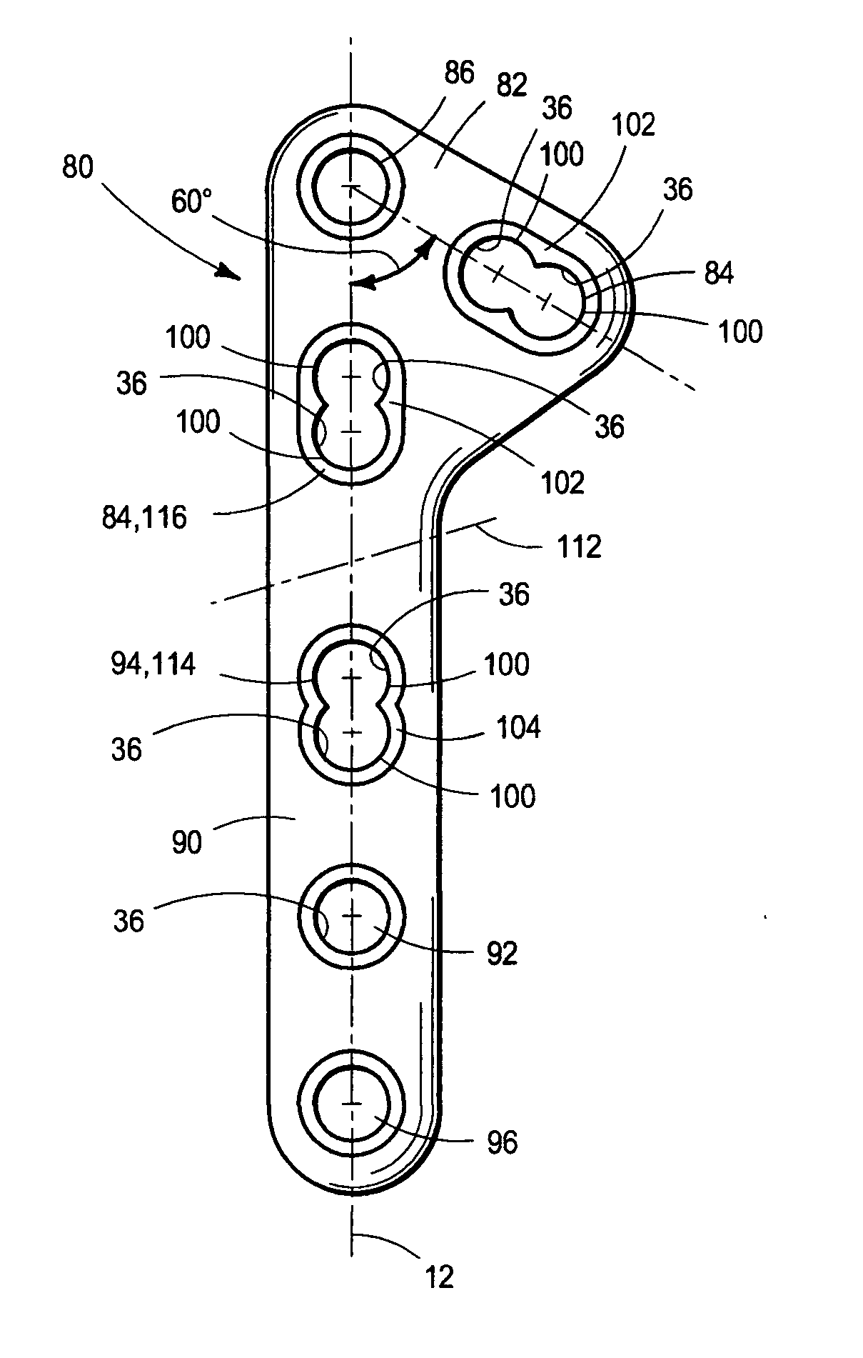
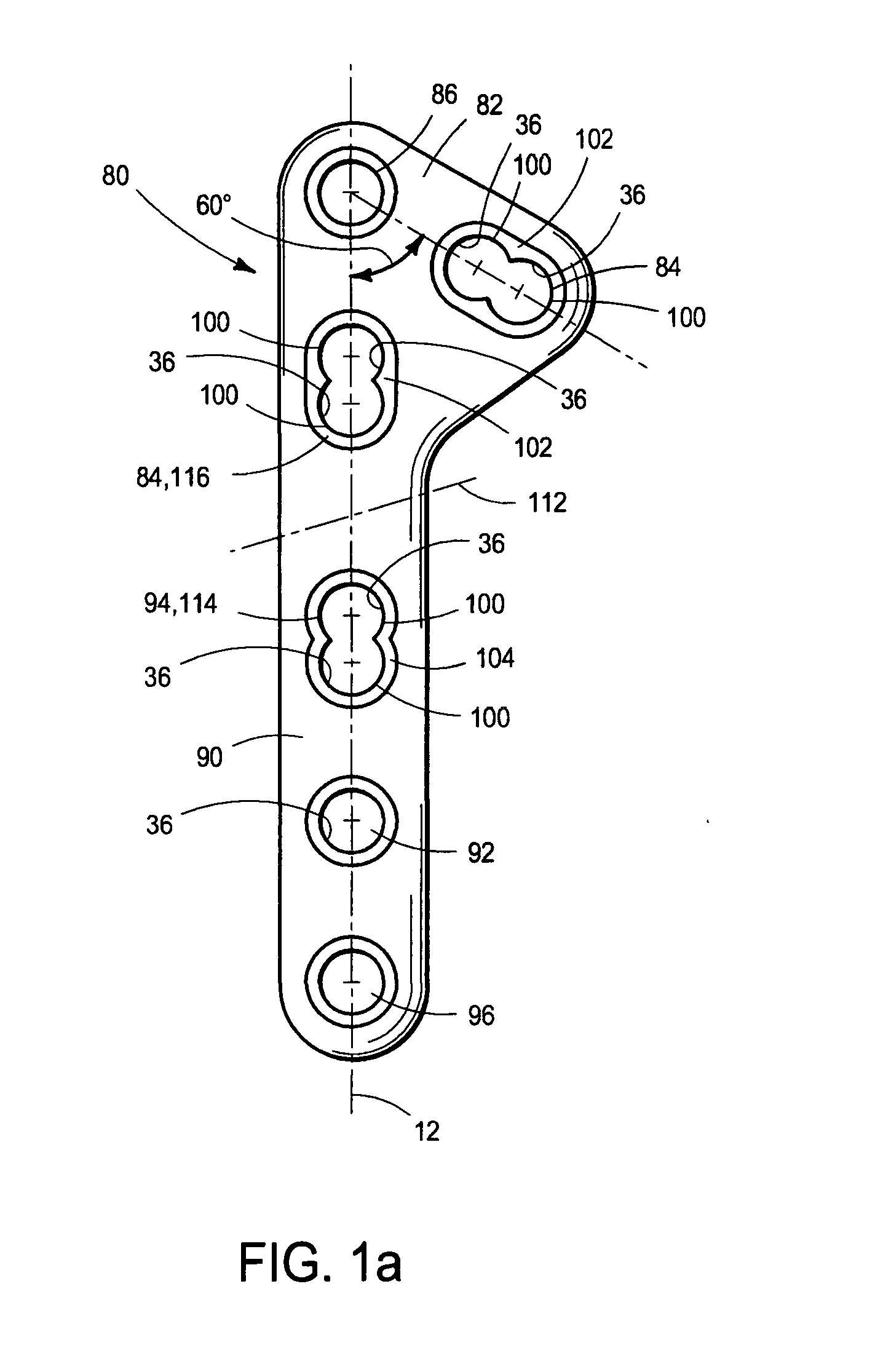
[0038] Note that the threaded apertures 100 used in the invention provide hole centers located at specific locations (as opposed to apertures that are formed as a slot). Use of threads centered at a specific point allows the bone screw to be fixed at a specific location at which the surgeon may judge the bone structure to be best suited to support such a bone screw. Unlike designs using a slot, the apertures 100 of the invention eliminate wander of the screw in the aperture. This further permits placement at specific locations for buttressing and / or secure fixing in neutral screw loading areas.

[0039] Referring now to FIGS. 4a and 4b, in another embodiment, the bone plate 80′ has a round hole 150 having a countersink 152 whose axis 154 is a...


PUM


Abstract

A bone plate(s) of complex form is provided, particularly suited to tibial plateau-leveling osteotomy and a distal femoral osteotomy. The bone plate has a main longitudinal axis, a bone-contacting bottom side (not shown) and a top side with at least three sets of overlapping holes which communicate through the plate from the top to the bottom side. The sets of overlapping holes define threaded apertures having multifaceted surfaces. When applied to a bone, two sets of such overlapping holes are located so as to lie on opposite sides of an osteotomy site and on the tibial plate; a third is aligned at approximately 60 degrees with the longitudinal axis. The configuration of this complex bone plate vary, depending on the physiology of the patient. An object of the invention is to provide an orthopaedic surgeon greater flexibility of choice in that a threaded peg providing secure fixing can be positioned at any interval along the bone plate, including at its extreme ends or on its elbow.

Description

CROSS-REFERENCE TO RELATED APPLICATIONS [0001] The contents of the U.S. provisional priority application Ser. No. 60 / 457,786, of the same title, filed on Mar. 26, 2003, are incorporated herein by reference hereto.BACKGROUND OF THE INVENTION [0002] This invention relates to devices, implants and prostheses used in orthopaedic surgery, and, more particularly, to bone plates used to reinforce fractured bones and thus promote healing. [0003] A compressive screw system, also known as the DCS system, is a bone plate system that has been used in trauma surgery for many years. The procedures for use of this system are well documented by the AO Institute, an institute having as one of its goals, the promotion of new orthopaedic surgical procedures. This system included a bone plate having slots communicating therethrough. A land in which the slot is wider at one end defines a stepped surface adjacent the portion of the slot that extends through the bone plate. The stepped surface is generall...

Claims


Application Information

Patent Timeline
IPC IPC(8): A61B17/80
CPCA61B17/8014A61B17/8052A61B17/8095A61B17/8061A61B17/8057
Inventor YOUNG, ROBERT ALLANWHITE, PATRICK MICHELKHOWAYLO, MICHAEL
Owner VIANT AS&O HLDG LLC
Why Eureka
Try Eureka