Torque sensor and electric streering device using the same

a technology of torque sensor and electric streering device, which is applied in the direction of instruments, force/torque/work measurement apparatus, transportation and packaging, etc., can solve the problems of downsizing or miniaturizing, and the inability to detect the torque correctly

Inactive Publication Date: 2005-02-03
TOYODA MASCH WORKS LTD
View PDF7 Cites 9 Cited by
  • Summary
  • Abstract
  • Description
  • Claims
  • Application Information

AI Technical Summary

Benefits of technology

It is also a primary object of the present invention to provide an improved torque sensor capable of downsizing or miniaturizing the construction of means for preventing a torsion bar from being twisted excessively.

Problems solved by technology

However, in the torque sensor of the aforementioned type, when the torsion bar is twisted beyond a predetermined angle, there arises a problem that the torque cannot be detected correctly because the difference between the electrical angles with the torsion bar twisted in a positive-going direction may become the same as that therebetween with the torsion bar twisted in a negative-going direction.
Further, in the aforementioned torque sensor, it is required to provide means for preventing the torsion bar from being twisted excessively, in which case it becomes a problem how to make such means downsized or miniaturized.

Method used


Image

  • Torque sensor and electric streering device using the same
  • Torque sensor and electric streering device using the same
  • Torque sensor and electric streering device using the same

Examples


Embodiment Construction

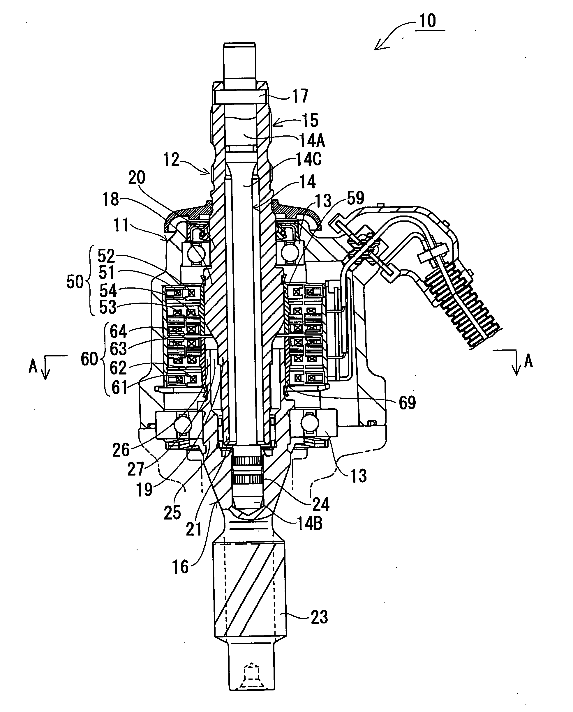
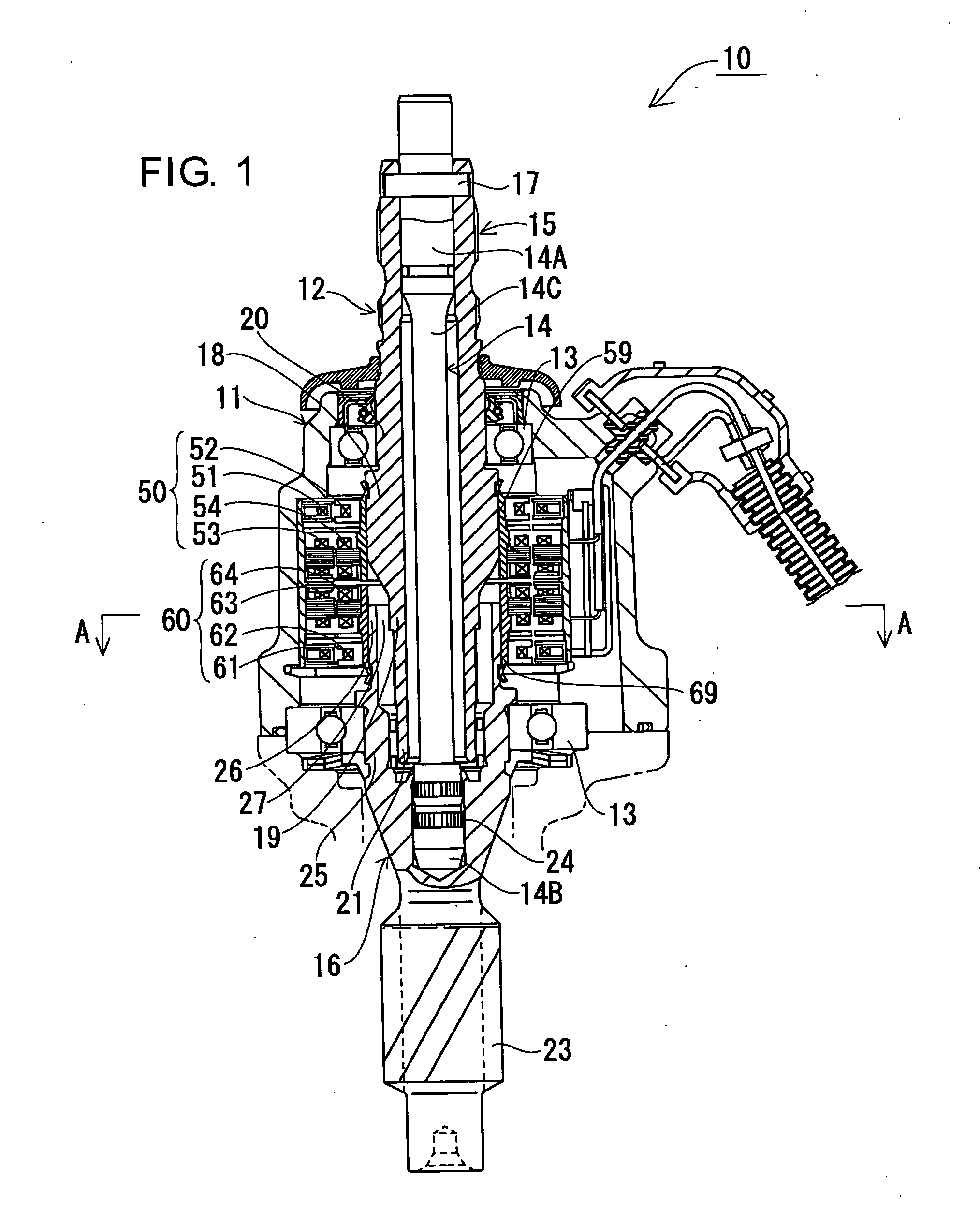
Hereafter, a torque sensor and an electric steering device in one embodiment according to the present invention will be described with reference to FIGS. 1 to 5. FIG. 1 shows the general construction of a torque sensor 10 in one embodiment. In FIG. 1, a numeral 11 denotes a cylindrical body, inside which a rotary shaft section 12 passes through and is rotatably supported by means of bearings 13, 13 provided at axial opposite end portions of the cylindrical body 11.

The rotary shaft section 12 is composed of a torsion bar 14 and first and second elongate sleeves 15, 16. An axial mid portion 14C of the torsion bar 14 is made thinner in diameter than the axial opposite ends portions 14A, 14B to be torsionally deformed when a load torque is applied on the torsion bar 14.

The first elongate sleeve 15 encircles almost the entire length of the mid portion 14C with a play and is snugly fit on one end portion 14A of the torsion bar 14 without a substantial clearance therebetween. Hereinaf...


PUM

PropertyMeasurementUnit
electrical angleaaaaaaaaaa
torsional angleaaaaaaaaaa

Abstract

A torque sensor is provided with a torsion bar, first and second elongate sleeves respectively secured to one and the other ends of the torsion bar, and a pair of resolvers respectively mounted on the first and second elongate sleeves. First and second stop portions are provided respectively at overlapping portions of the first and second elongate sleeves where the second elongate sleeve is fit partly on the external surface of the first elongate sleeve with a play. A rotary sleeve given to one of the resolvers is press-fit on the external surface of the stop portion provided on the second elongate sleeve for mounting one of the resolvers thereon as well as for reinforcing the mechanical strength of the stop portion provided on the second elongate sleeve. Further, the resolvers used therein are chosen as those respectively having n-poles and m-poles. Where the torsional angle of the torsion bar is represented by symbol “θ”, the first and second stop portions are constructed to satisfy an expression (θ<180·|1 / n−1 / m|). The torsional angle of the torsion bar is limited to being smaller than the angle determined by the expression, and hence, the resolvers are prevented from having the same values in their electrical angles, so that incorrect detection in torque can be obviated.

Description

INCORPORATION BY REFERENCE This application is based on and claims priority under 35 U.S.C. sctn. 119 with respect to Japanese Applications No. 2003-087072 and No. 2003-087073 both filed on Mar. 27, 2003, the entire contents of which are incorporated herein by reference. BACKGROUND OF THE INVENTION 1. Field of the Invention The present invention relates to a torque sensor capable of detecting a torque by detecting the torsional angle of a torsion bar by the use of a pair of resolvers. It also relates to an electric steering device provided with such a torque sensor. 2. Discussion of the Related Art As described for example in Japanese unexamined, published patent application No. 10-328952 (1998-328952), a resolver is provided on a servomotor and works to detect the rotational angle thereof. In recent years, there has been under development a torque sensor which is capable of detecting the torsional angle of a torsion bar provided inside a cylindrical body, in the form of electr...

Claims


Application Information

Patent Timeline
Patent Type & Authority Applications(United States)
IPC IPC(8): B62D6/10G01L3/10G01L5/22
CPCB62D6/10G01L3/109G01L5/221
Inventor NARUSE, MITSUNORIYOSHIZAWA, YUJIMOCHIZUKI, YUSUKE
Owner TOYODA MASCH WORKS LTD
Why Eureka
Try Eureka