Method and apparatus for lighting high pressure discharge lamp, high pressure discharge lamp apparatus, and projection-type image display apparatus

a technology of high pressure discharge and lamp, which is applied in the direction of electric variable regulation, process and machine control, instruments, etc., can solve the problems of reducing the light rise time, requiring a long time from the start of discharge, and the size of high pressure discharge lamps is large, so as to reduce the light rise time

Active Publication Date: 2005-02-03
PANASONIC CORP
View PDF8 Cites 23 Cited by
  • Summary
  • Abstract
  • Description
  • Claims
  • Application Information

AI Technical Summary

Benefits of technology

[0031] With the above-stated construction, a projection-type image display apparatus with reduced light rise time is provided.

Problems solved by technology

On the other hand, a problem of such high pressure discharge lamps is that they require a long time from a start of discharge until they obtain a luminous flux that has a certain level of brightness (hereinafter, the time required for obtaining such a luminous flux is referred to as “light rise time”).
Reducing the light rise time has been a longstanding challenge in the field of the high pressure discharge lamp.
However, high pressure discharge lamps become larger in size as they become higher in power.
This decreases the speed at which the light-emitting metal evaporates in the discharge space, further prolonging the light rise time.
However, if the above-mentioned technologies for motor vehicles are applied to high pressure discharge lamps for projectors, edges of the lamp electrodes would melt.
This is a serious damage to the electrodes and lamps.
However, reduction in the distance between electrodes leads to a larger amount of lamp current flowing there.
Also, supply of an excessively high power may lead to an excessive increase of the lamp current.
Accordingly, if a power much higher than a power at a normal lighting is supplied to a high pressure discharge lamp for a projector under the same condition as a high pressure discharge lamp for a motor vehicle, the temperature at edges of electrodes would increase abnormally, melting the electrodes.
When this happens, an appropriate point light source is not obtained, and in the worst case, a lighting failure occurs.
However, as described earlier, high pressure discharge lamps for projectors are relatively large in size, and therefore it is difficult to introduce a rare gas at a pressure higher than a certain pressure, from a viewpoint of the manufacturing technology.
In such circumstances, it is extremely difficult to reduce the light rise time.

Method used


Image

  • Method and apparatus for lighting high pressure discharge lamp, high pressure discharge lamp apparatus, and projection-type image display apparatus
  • Method and apparatus for lighting high pressure discharge lamp, high pressure discharge lamp apparatus, and projection-type image display apparatus
  • Method and apparatus for lighting high pressure discharge lamp, high pressure discharge lamp apparatus, and projection-type image display apparatus

Examples


experiment 1

[0077] An experiment was conducted to determine the optimum range for the voltage Va for the high pressure mercury lamp 100 rated as 200 W.

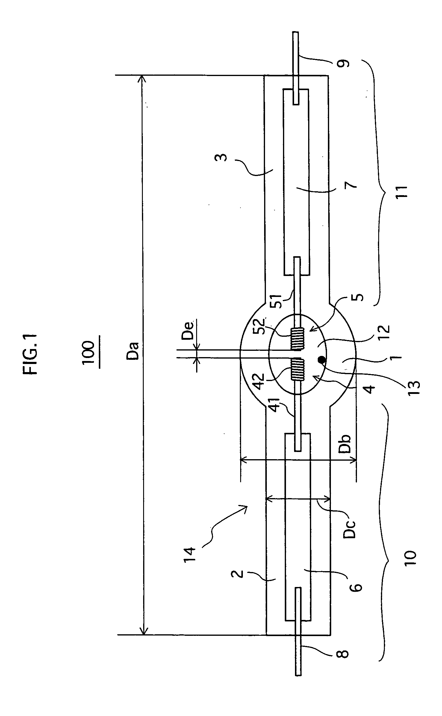
[0078] The lamps used in this experiment as the test pieces are high pressure mercury lamps having the construction shown in FIG. 1. Specifications of the lamps are as follows. [0079] Amount of mercury contained in the discharge space: 200 mg / cm3 per inner capacity [0080] Pressure at which rare gases are introduced into the space at ordinary temperature: 30 kPa [0081] Inter-electrode distance De: 1.5 mm [0082] Lamp entire length Da: 90 mm [0083] Light-emitting portion external diameter Db: 13 mm [0084] Seal portion external diameter Dc: 8.0 mm

[0085] Each electrode has an electrode rod around which an eight-turn double coil is formed. The electrode rod diameter d1 (see FIG. 6A) is set to 0.4 mm. The wire diameter d2 of the electrode coil is set to 0.25 mm.

[0086]FIG. 5 shows levels of damage to electrodes that were observed after the experiment ...


PUM


Abstract

A lighting method for a high pressure discharge lamp in which a high-pressure pulse is applied to cause a dielectric breakdown, and then in step S1, it is judged whether the lamp voltage is higher than 25 volts as the current switching voltage. If it is judged negatively in step S1, the control circuit 304 performs a constant current control with the current limiting level set to 6 amperes (step S2). If it is judged that the lamp voltage is higher than 25 in step S1, the control circuit 304 performs a constant current control with the current limiting level set to 4 amperes (step S3). When the lamp voltage rises and reaches 50 volts, the control circuit 304 performs a constant power control so that the lamp power remains to be 200W.

Description

BACKGROUND OF THE INVENTION [0001] (1) Field of the Invention [0002] The present invention relates to a method and an apparatus for lighting a high pressure discharge lamp, a high pressure discharge lamp apparatus, and a projection-type image display apparatus. [0003] (2) Description of the Related Art [0004] High pressure discharge lamps such as high pressure mercury lamps or metal halide lamps generally provide highly bright luminous flux, which is regarded as an excellent advantageous effect thereof. On the other hand, a problem of such high pressure discharge lamps is that they require a long time from a start of discharge until they obtain a luminous flux that has a certain level of brightness (hereinafter, the time required for obtaining such a luminous flux is referred to as “light rise time”). Reducing the light rise time has been a longstanding challenge in the field of the high pressure discharge lamp. [0005] Especially, projection-type image display apparatuses (hereinaft...

Claims


Application Information

Patent Timeline
Patent Type & Authority Applications(United States)
IPC IPC(8): H05B41/282H05B41/292H05B41/38
CPCH05B41/2928Y02B20/204H05B41/388Y02B20/00H05B41/282
Inventor ONO, SYUNSUKEOZASA, MINORUYAMAMOTO, MASAHIRO
Owner PANASONIC CORP
Why Eureka
Try Eureka