Can shell and double-seamed can end

Inactive Publication Date: 2005-02-10
BALL CORP +1
View PDF24 Cites 88 Cited by
  • Summary
  • Abstract
  • Description
  • Claims
  • Application Information

AI Technical Summary

Benefits of technology

[0005] The present invention is directed to an improved sheet metal shell and can end and a method of forming the can end which provides the desirable features and advantages mentioned above, including a significant reduction in the blank diameter for forming a can shell and a significant increase in strength/weight r

Problems solved by technology

While some of the can shells and can ends disclosed in the above patents provide som

Method used


Image

  • Can shell and double-seamed can end
  • Can shell and double-seamed can end
  • Can shell and double-seamed can end

Examples


Embodiment Construction

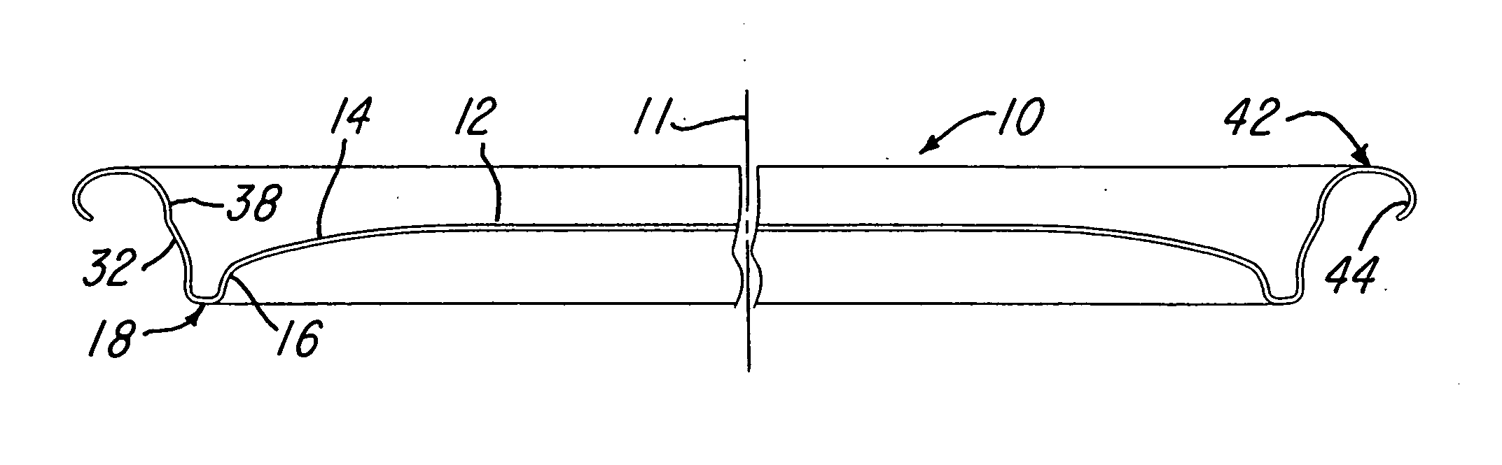
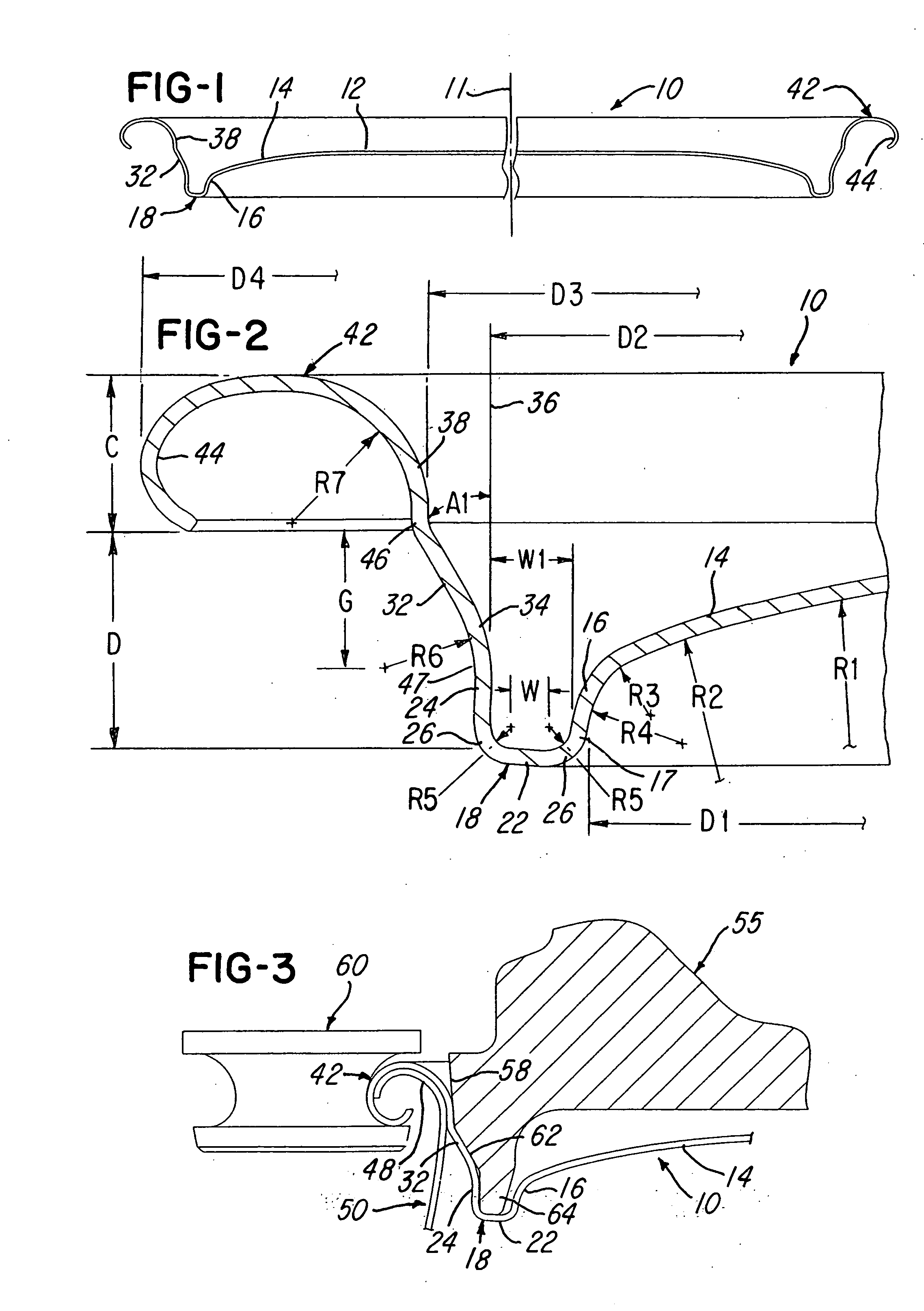
[0022]FIG. 1 illustrates a one-piece shell 10 which is formed from a substantially circular blank of sheet metal or aluminum, preferably having a thickness of about 0.0085 inch and a blank diameter of about 2.705 inches. The shell 10 has a center axis 11 and includes a slightly crowned center panel 12 with an annular portion 14 extending to a curved panel wall 16. The center panel wall portion 14 and panel wall 16 may be formed by a series of blended curved walls having radii wherein R1 is 1.489 inch, R2 is 0.321 inch, R3 is 0.031 inch, and R4 is 0.055 inch. The curved panel wall 16 has a bottom inner diameter D1 of about 1.855 inch.

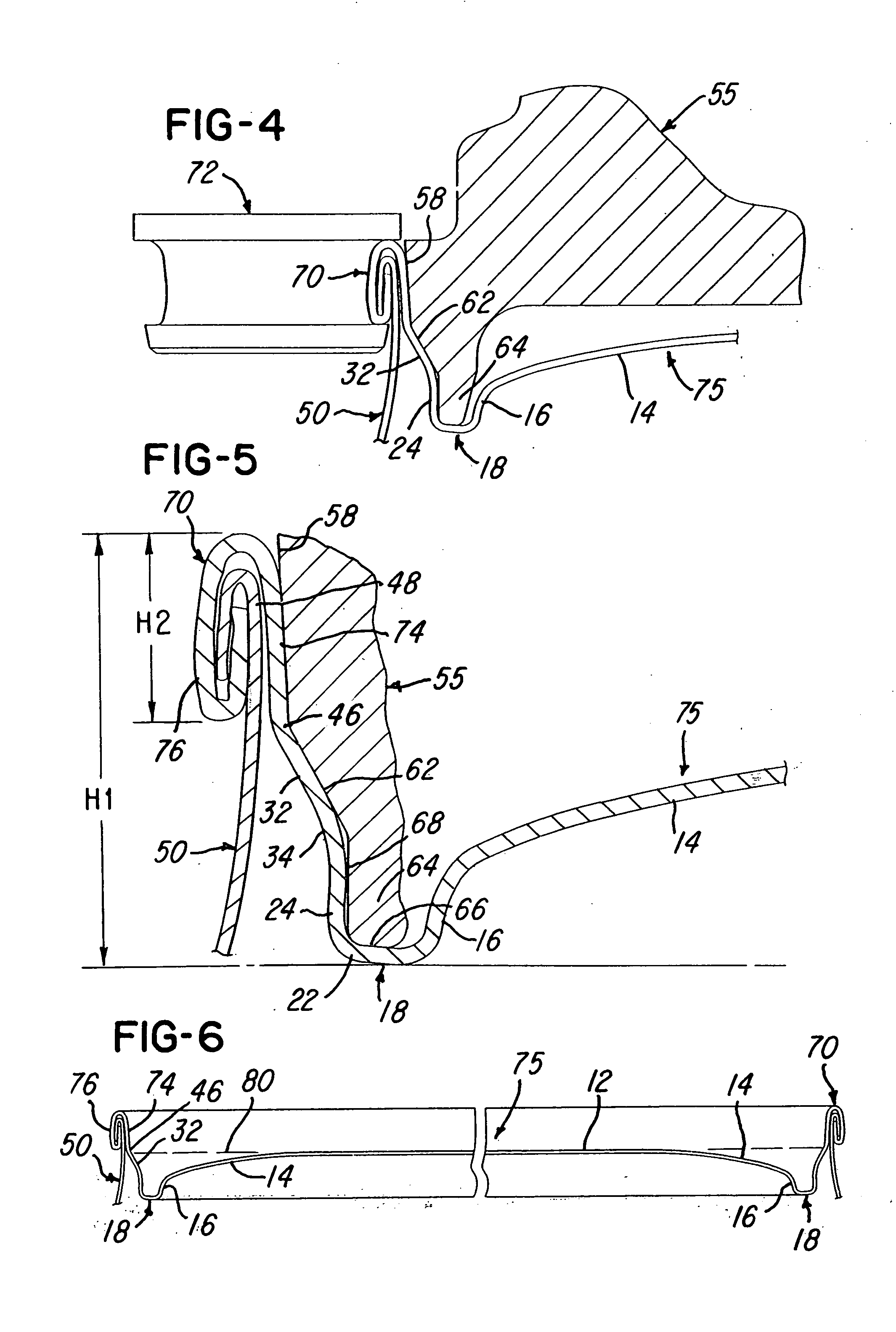
[0023] The curved panel wall 16 with the radius R4 extends from an inner wall 17 of a reinforcing rib or countersink 18 having a U-shaped cross-sectional configuration and including a flat annular bottom wall 22 and a generally cylindrical outer wall 24 having an inner diameter D2, for example, of about 1.957 inches. The flat bottom wall 22 of the count...


PUM

PropertyMeasurementUnit
Lengthaaaaaaaaaa
Lengthaaaaaaaaaa
Angleaaaaaaaaaa

Abstract

A drawn aluminum can shell has a peripheral crown which is double-seamed with an end portion of an aluminum can body to provide a can end having a generally flat center panel connected by an inclined curved or straight panel wall to an inclined inner wall of an annular U-shaped countersink. The countersink has an outer wall which connects with an inclined lower wall portion of a chuckwall at a junction below the center panel, and the chuckwall has a curved or inclined upper wall portion which connects with an inner wall of the crown. The chuckwall also has an intermediate wall portion forming a break, and the inner bottom width of the countersink is less than the radial width of the panel wall. The inclined upper wall portion of the chuckwall extends at an angle greater than the angle of the inclined lower wall portion of the chuckwall.

Description

RELATED APPLICATION [0001] This application is a continuation-in-part of application Ser. No. 10 / 361,245, filed Feb. 10, 2003, which is a continuation-in-part of Ser. No. 10 / 078,152, filed Feb. 19, 2002, U.S. Pat. No. 6,516,968, which is a continuation-in-part of application Ser. No. 09 / 898,802, filed Jul. 3, 2001, U.S. Pat. No. 6,419,110.BACKGROUND OF THE INVENTION [0002] This invention relates to the construction or forming of a sheet metal or aluminum can shell and can end having a peripheral rim or crown which is double-seamed to the upper edge portion of a sheet metal or aluminum can body. Such a can end is formed from a drawn sheet metal can shell, for example, a shell produced by tooling as disclosed in applicant's U.S. Pat. No. 5,857,374 the disclosure of which is herein incorporated by reference. Commonly, the formed can shell includes a circular center panel which extends to a panel wall which extends to or also forms the inner wall of a reinforcing rib or countersink havi...

Claims


Application Information

Patent Timeline
IPC IPC(8): B21D31/02B21D51/32B21D51/38B21D51/44B65DB65D8/12
CPCB21D51/32B21D51/38B65D7/12B65D2517/0062B65D7/44B65D17/08B65D7/36B21D51/44
Inventor STODD, R. PETERBATHURST, JESS N.
Owner BALL CORP
Why Eureka
Try Eureka