Optical signal transmission system

a transmission system and optical signal technology, applied in the direction of instruments, semiconductor lasers, cladded optical fibres, etc., can solve the problems of high cost, difficult coupling of vcsel light sources to the end face of light guide paths, and generation of transmission loss, so as to reduce the loss of transmission signal light beams and facilitate the effect of performan

Inactive Publication Date: 2005-02-10
FUJIFILM HLDG CORP +1
View PDF10 Cites 15 Cited by
  • Summary
  • Abstract
  • Description
  • Claims
  • Application Information

AI Technical Summary

Benefits of technology

[0012] Since VCSEL having the plurality of light-emission points is used in the optical signal transmission system, assuming that optical output is the same at each light-emission point, when VCSEL having the plurality of light-emission points is compared with VCSEL having one light-emission point, heat generation per light-emission point can be reduced in VCSEL having the plurality of light-emission points, and the longer life of VCSEL can be realized.
[0048] (2) Because the core diameter of the refractive-index profile optical fiber is set to not lower than 200 μm, the coupling loss for the axial shift during the coupling can be prevented from worsening, the alignment between the refractive-index profile optical fiber and VCSEL and the alignment between the refractive-index profile optical fiber and the light receiving element also become easier, and the generation of the mode noise can be prevented. The mode noise is easy to generate; when the core diameter is smaller and the axial shift during the coupling is larger. Therefore, influence of the axial shift can be suppressed by increasing the core diameter. The mode noise can be observed by an S / N ratio or the spread of an eye in an eye pattern.

Problems solved by technology

In a perfluorinated optical fiber which is used in GI-POF (Graded Index type Plastic Optical Fiber), transmission loss is generated because mode noise is generated in the optical fiber having a relatively small diameter.
Further, because the optical fiber has such a small diameter, efficient coupling from the plurality of VCSEL light sources to the end face of the light guide path is difficult, and cost becomes higher.

Method used


Image

  • Optical signal transmission system
  • Optical signal transmission system
  • Optical signal transmission system

Examples


example 1

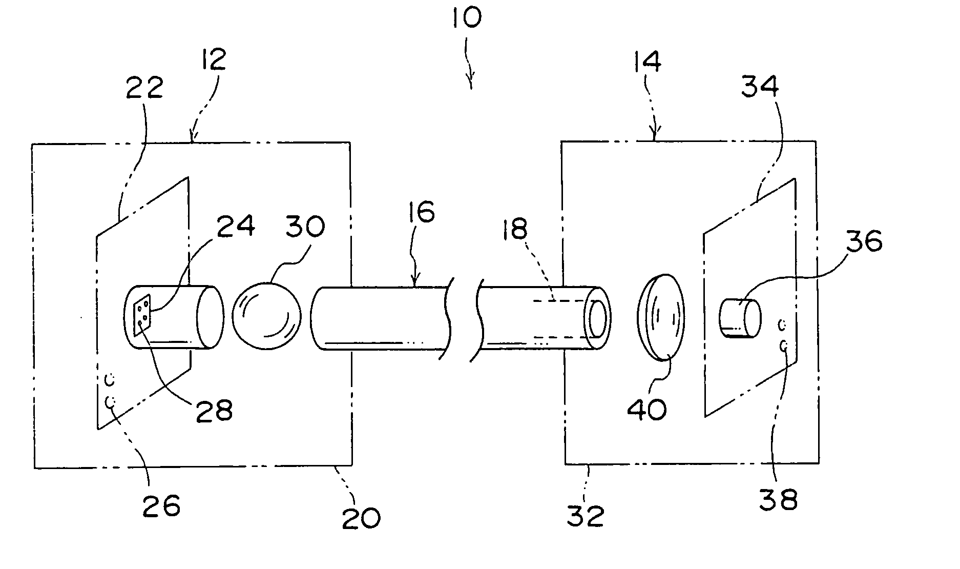
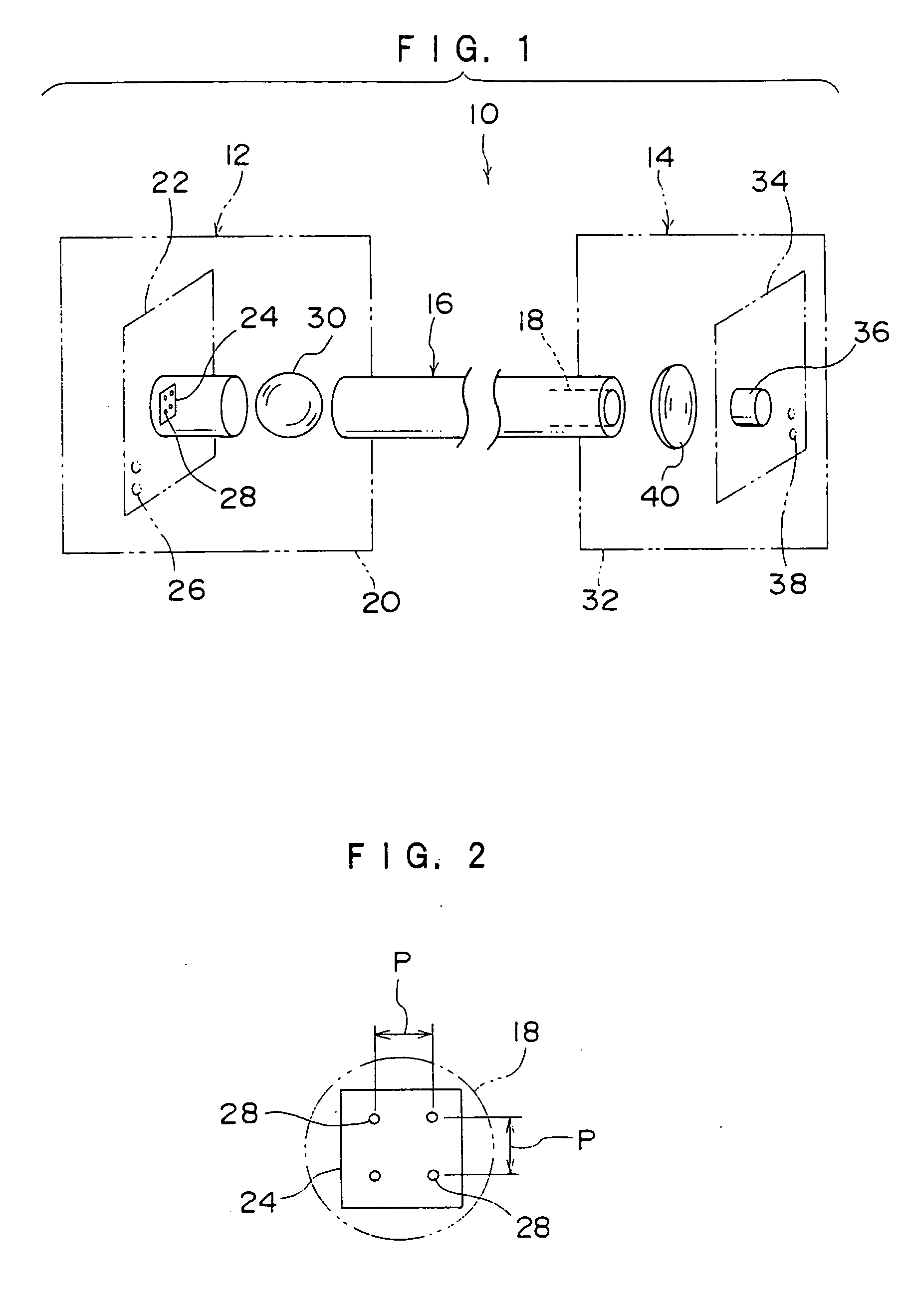
[0111] The optical fiber having the central wavelength of 780 nm is used for VCSEL.

[0112] The number of light-emission points is four (two-by-two lattice shape) and the light-emission points were arranged with the pitch of 50 μm.

[0113] The following composition materials were used for making GI-POF.

[0114] The production of GI-POF which uses MMA-d8 as a raw material will be described.

[0115] The vinylidene fluoride resin pipe is produced by the extrusion with KF-850 (product of Kureha Chemical Industry Co., Ltd.), the inner diameter of the pipe is 22 mm, the length is 600 mm, and a bottom portion of the pipe is also made of KF-850. A predetermined amount of deuterated methyl methacrylate (MMA-d8) is injected into the vinylidene fluoride resin pipe. In the deuterated methyl methacrylate, hydroquinone monomethyl ether as a polymerization inhibitor is removed and moisture content is removed up to not more than 80 ppm.

[0116] A mixed solution, in which 0.5% by mass dimethyl azobisisob...


PUM


Abstract

In an optical signal transmission system which can perform high-speed optical transmission not lower than 1 Gbps, VCSEL has light-emission points. A core diameter of an optical fiber GI-POF is set to not lower than 200 μm, and the light-emission points of VCSEL are arranged inside an outer periphery at an end face of GI-POF. A polymerization composition material constituting the core of GI-POF is made of a compound containing deuterated poly methacrylic ester. A wavelength of the light beam of VCSEL is set to the range of 770 nm to 810 nm.

Description

CROSS-REFERENCE TO RELATED APPLICATION [0001] This application claims priority under 35 USC 119 from Japanese Patent Applications No. 2003-274332 and No. 2004-177296, the disclosure of which is incorporated by reference herein. BACKGROUND OF THE INVENTION [0002] 1. Field of the Invention [0003] The present invention relates to an optical signal transmission system, particularly to the optical signal transmission system which enables high-speed optical data transmission more than 1 Gbps (bit per second). [0004] 2. Description of the Related Art [0005] In the optical signal transmission system, in order to lengthen lifetime of a vertical cavity surface emitting laser diode (hereinafter referred to as VCSEL) light source and in order to cover output of VCSEL even if electric current is lowered, an example is Japanese Patent Application Laid-Open (JP-A) No. 2003-152284. This discloses a system in which a plurality of light sources is used and the light sources are arranged within the ra...

Claims


Application Information

Patent Timeline
Patent Type & Authority Applications(United States)
IPC IPC(8): G02B6/028G02B6/26G02B6/42H01L31/0232H01S5/022H01S5/42H04B10/25H04B10/2507H04B10/2581
CPCG02B6/02038H04B10/2581G02B6/425G02B6/0288G02B6/26G02B6/42H01S5/42
Inventor OHASHI, YUICHIMATSUMOTO, KENJIHIIRO, HIROYUKINAKAMURA, YOSHISADAKATO, MIKIHIKOUENO, OSAMUHAMADA, TSUTOMUKYOZUKA, SHINYANAKAYAMA, HIDEOBABA, TOMO
Owner FUJIFILM HLDG CORP
Why Eureka
Try Eureka