Padlock

a technology of padlocks and locks, applied in the field of padlocks, can solve the problems of travelers losing their properties in travel baggage boxes, travelers without knowing the security number, and unable to unlock their baggage boxes,

Inactive Publication Date: 2005-03-03
YU CHUN TE
View PDF11 Cites 70 Cited by
  • Summary
  • Abstract
  • Description
  • Claims
  • Application Information

AI Technical Summary

Benefits of technology

[0003] It is therefore an objective of the present invention to provide a padlock that can be unlocked by the owner of the padlock by dialing an unlocking number or by authorized security personals with a general key.

Problems solved by technology

Thereby others without knowing the security number cannot unlock his baggage box.
However terrorists may use travel baggage boxes to deliver explosive devices to endanger people's safety.
The travelers may lose their properties in their travel baggage boxes if they leave their travel baggage boxes unlocked.
There is a dilemma between travelers' rights and flight safety.

Method used


Image

  • Padlock
  • Padlock
  • Padlock

Examples


first embodiment

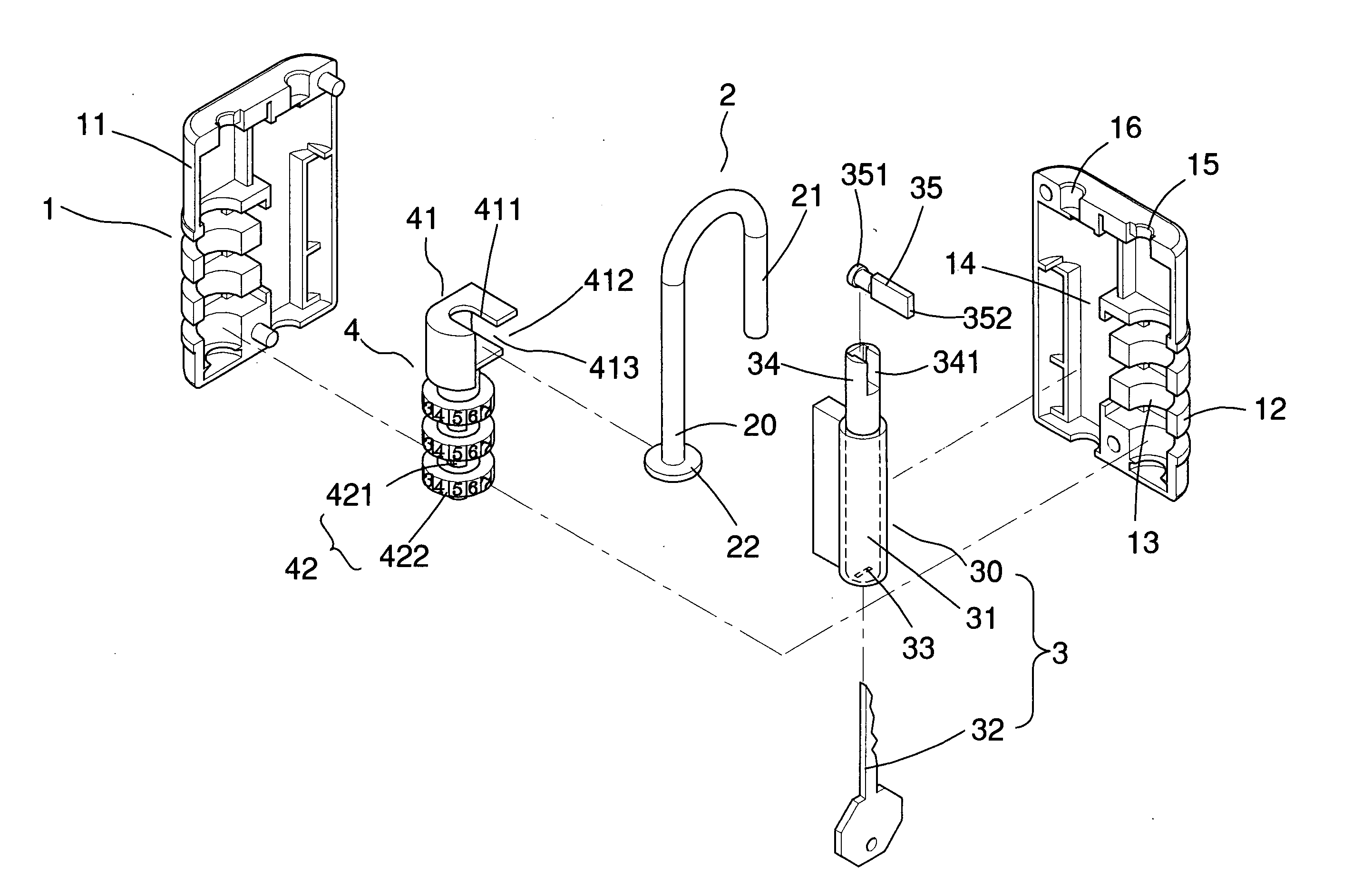
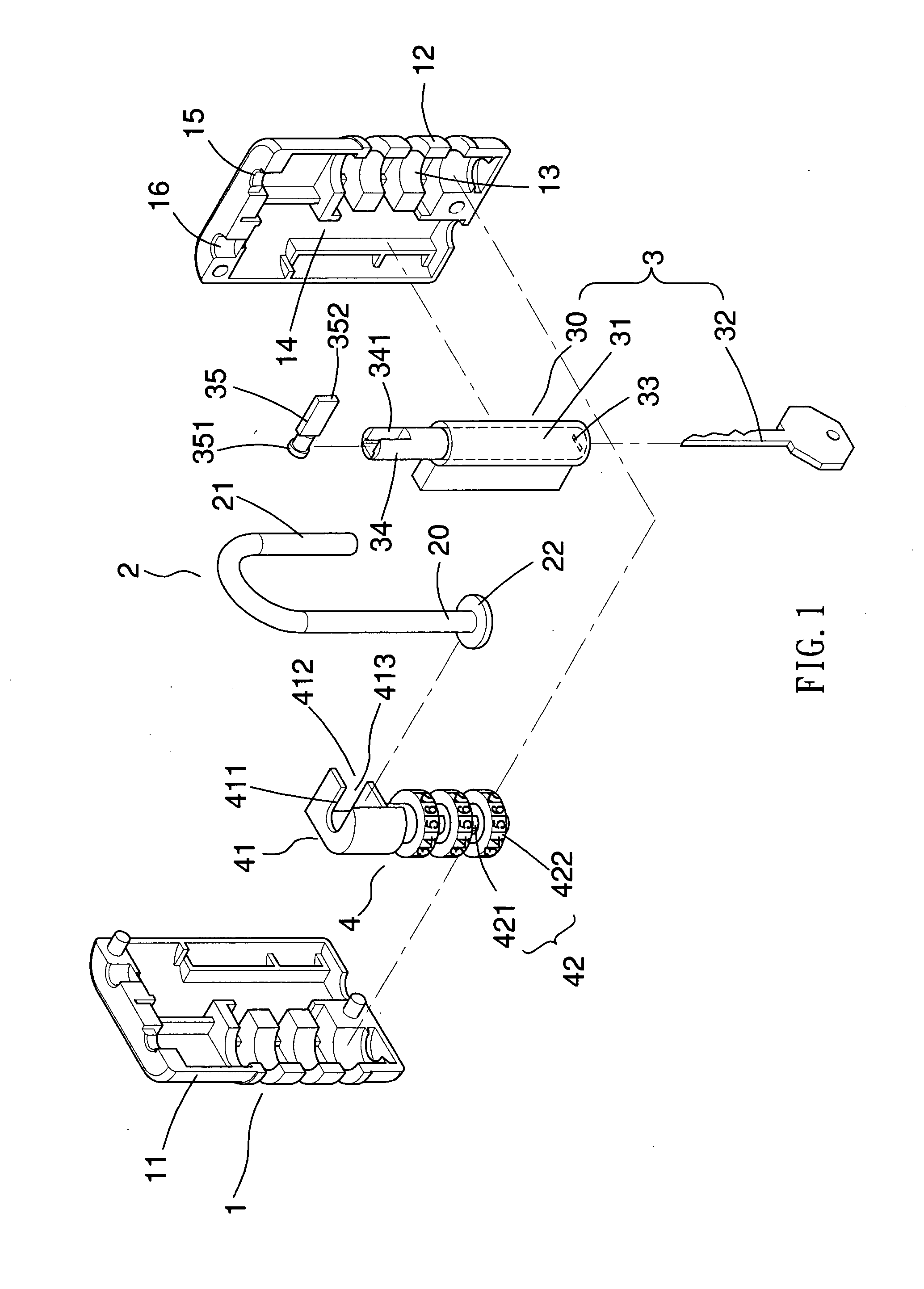
[0033] With reference to FIG. 1 to FIG. 6, the padlock of the present invention mainly contains a lock body 1, a shackle 2, a private locking means 4 and a general locking means 3. The lock body 1 contains a front cover 11 and a back cover 12 engaged with the front cover 11. The lock body 1 has a first chamber 13 and a second chamber 14 therein. The lock body 1 has a receptacle 16 thereon and a hole 15 communicable to the first chamber 13. The shackle 2 has a longer arm 20 and shorter arm 21. The longer arm 20 is slidably received in the first chamber 13 through the hole 15 of the lock body 1. The longer arm 20 has a stop 22 at an end thereof and the shorter arm 21 is engagable with the receptacle 16 of the lock body 1. The private locking means 4 is formed in the first chamber 13. The private locking means 4 contains a frame 41 and mechanism 42. The frame 41 has a sliding space 413 therein. The frame 41 has a first opening 411 on top thereof for receiving the end and the stop 22 of...

second embodiment

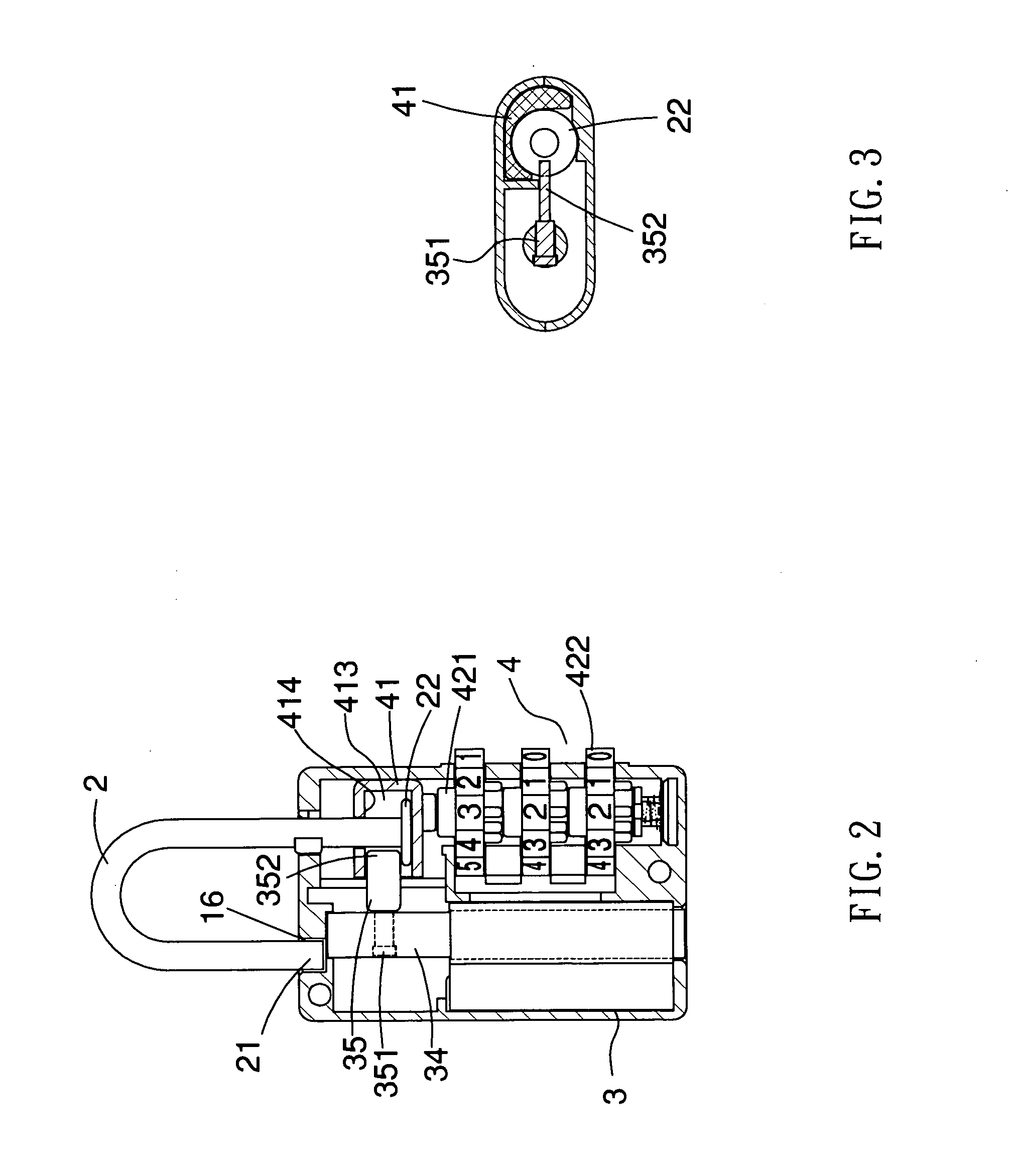
[0039] Referring to FIG. 8 and FIG. 9, the padlock of the second embodiment is locked. The key operated locking means 3a is not operated, so the end 352a of the engaging element 35a is placed between the inner top 414 of the frame 41 and the stop 22 to block the movement of the stop 22. Because the number wheels 422 are not dialed to the unlocking number, the stem 421 and the frame 41 connected thereto cannot move vertically. The frame 41 is positioned at the lowest point of its movement and the shorter arm 21 of the shackle 2 is placed within the receptacle 16.

[0040] With reference to and FIG. 10, the padlock of the second embodiment is unlocked by dialing the number wheels 422 to the unlocking number. Since the number wheels 422 of the combination locking means 4 are dialed to the unlocking number and the end 351a of the engaging element 35a is pivotally connected to a pivot 342a in the slot 341a of the driving rod 34a, the frame 41 connected to the stem 421 can move vertically to...

third embodiment

[0043] Referring to FIG. 13 and FIG. 14, the padlock of the third embodiment is locked.

[0044] The key operated locking means 3a is not operated, so the end 352a of the engaging element 35a is placed between the inner top 414 of the frame 41 and the stop 22 to block the movement of the stop 22. The stop 22 is holding in the lower bend 441 of the spring plate 44. Because the number wheels 422 are not dialed to the unlocking number, the stem 421 and the frame 41 connected thereto cannot move vertically. The frame 41 is positioned at the lowest point of its movement and the shorter arm 21 of the shackle 2 is placed within the receptacle 16.

[0045] With reference to FIG. 15, the padlock of the third embodiment is unlocked by dialing the number wheels 422 to the unlocking number. Since the number wheels 422 of the combination locking means 4 are dialed to the unlocking number and the end 351a of the engaging element 35a is pivotally connected to a pivot 342a in the slot 341a of the drivin...


PUM


Abstract

A padlock that can be unlocked by the owner of the padlock by dialing an unlocking number or by authorized security personals with a general key. The padlock mainly contains a lock body, a shackle, a private locking means and a general locking means. The lock body has a first chamber and a second chamber therein. The lock body has a receptacle thereon and a hole communicable to the first chamber. The shackle has a longer arm and shorter arm. The longer arm is slidably received in the first chamber through the hole of the lock body. The longer arm has a stop at an end thereof and the shorter arm is engagable with the receptacle of the block. The private locking means is formed in the first chamber. The private locking means contains a frame and mechanism. The frame has a sliding space therein. The frame has a first opening on top thereof for receiving the end and the stop of the longer arm in the sliding space. The mechanism is used for controlling movements of the frame. The frame is movable between the mechanism and the hole of the lock body. The general locking means is installed in the second chamber for controlling movements of the end and the stop of sad longer arm.

Description

TECHNICAL FIELD [0001] This invention relates generally to a padlock, in particular, to provide a padlock having a shackle locked by a key operated locking means at one end and a combination locking means at another end, thereby the padlock can be unlocked by using a key or by dialing the combination locking means to an unlocking number. BACKGROUND OF THE INVENTION [0002] Preventing personal stuffs from being lost or stolen, travelers usually lock their own travel baggage boxes. Combination lock is the most common lock that installed in a travel baggage box because it takes little space. Each traveler sets up his own security number for the combination lock. Thereby others without knowing the security number cannot unlock his baggage box. However terrorists may use travel baggage boxes to deliver explosive devices to endanger people's safety. Security personals in airports may need to exam travelers' travel baggage boxes in some circumstances without presence of the owners of the tr...

Claims


Application Information

Patent Timeline
Patent Type & Authority Applications(United States)
IPC IPC(8): E05B37/00E05B37/02E05B37/22
CPCE05B35/105E05B37/025E05B37/0034Y10T70/7141Y10T70/424Y10T70/7147
Inventor YU, CHUN TE
Owner YU CHUN TE
Why Eureka
Try Eureka