Electric padlock

a technology of electric padlocks and padlocks, which is applied in the field of electric padlocks, can solve the problems of inability to operate the electric operating unit, vandalism of electric padlocks,

Inactive Publication Date: 2005-05-31
EZ TREND TECH
View PDF11 Cites 45 Cited by
  • Summary
  • Abstract
  • Description
  • Claims
  • Application Information

AI Technical Summary

Benefits of technology

[0008]Accordingly, an electric padlock of the present invention comprises a lock casing, an inverted U-shaped shackle member, a latch member, and a battery cap member. The lock casing has an end wall formed with first and second shackle insert holes, a battery compartment that is adapted for receiving a battery unit, and a battery access hole that permits insertion of the battery unit into and removal of the battery unit from the battery compartment. The shackle member has first and second leg portions that are extended movably into the lock casing at the first and second shackle insert holes, respectively. One of the first and second leg portions is formed with a shackle groove. The latch member is received in the lock casing, and is movable between a lockin

Problems solved by technology

The conventional electric padlock is disadvantageous in that, since the battery cap member can be removed regardless of whether the shackle member is locked or unlocked from the lock casing, the electric padlock can be vandalized by simply rem

Method used


Image

  • Electric padlock
  • Electric padlock
  • Electric padlock

Examples


Embodiment Construction

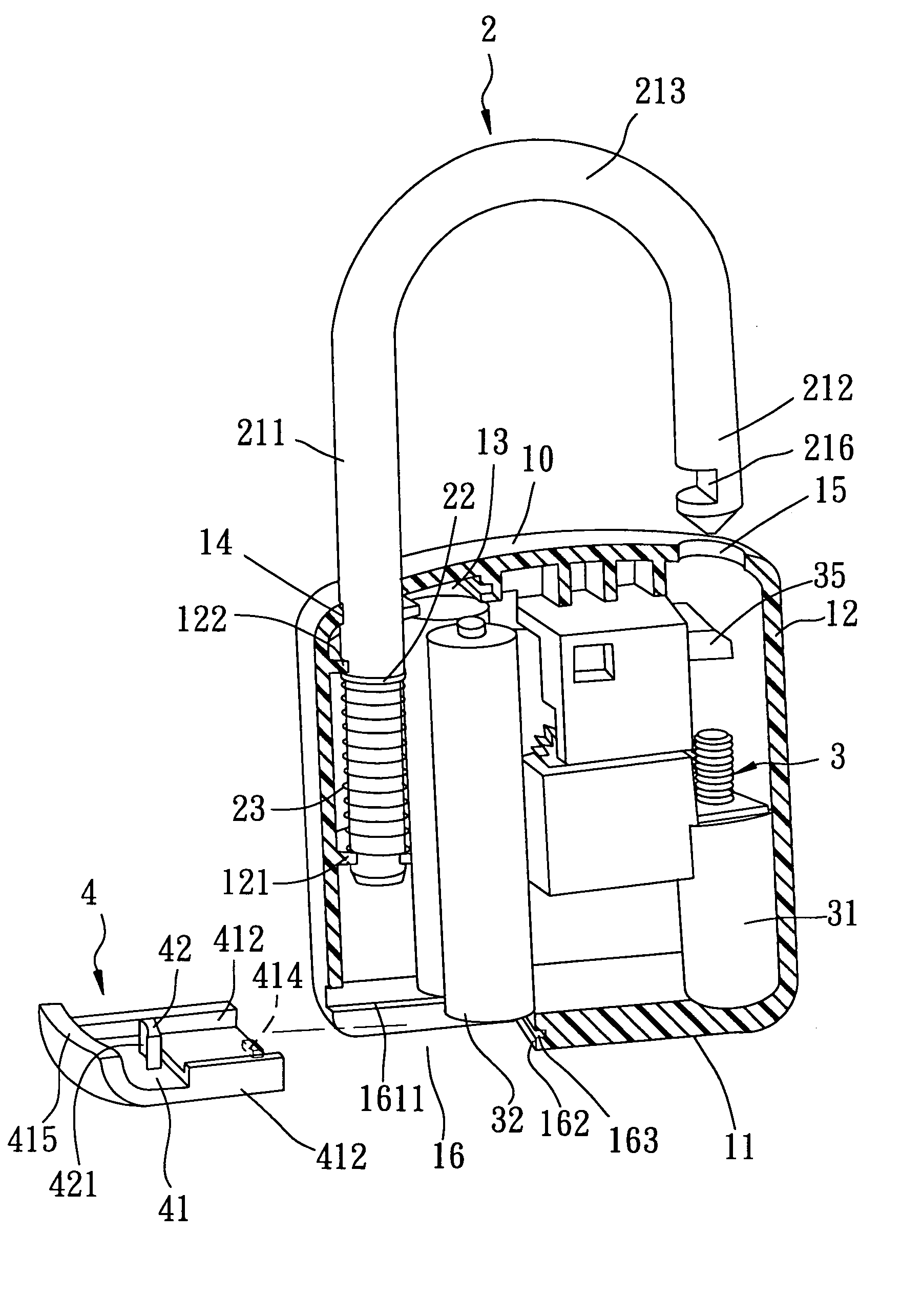
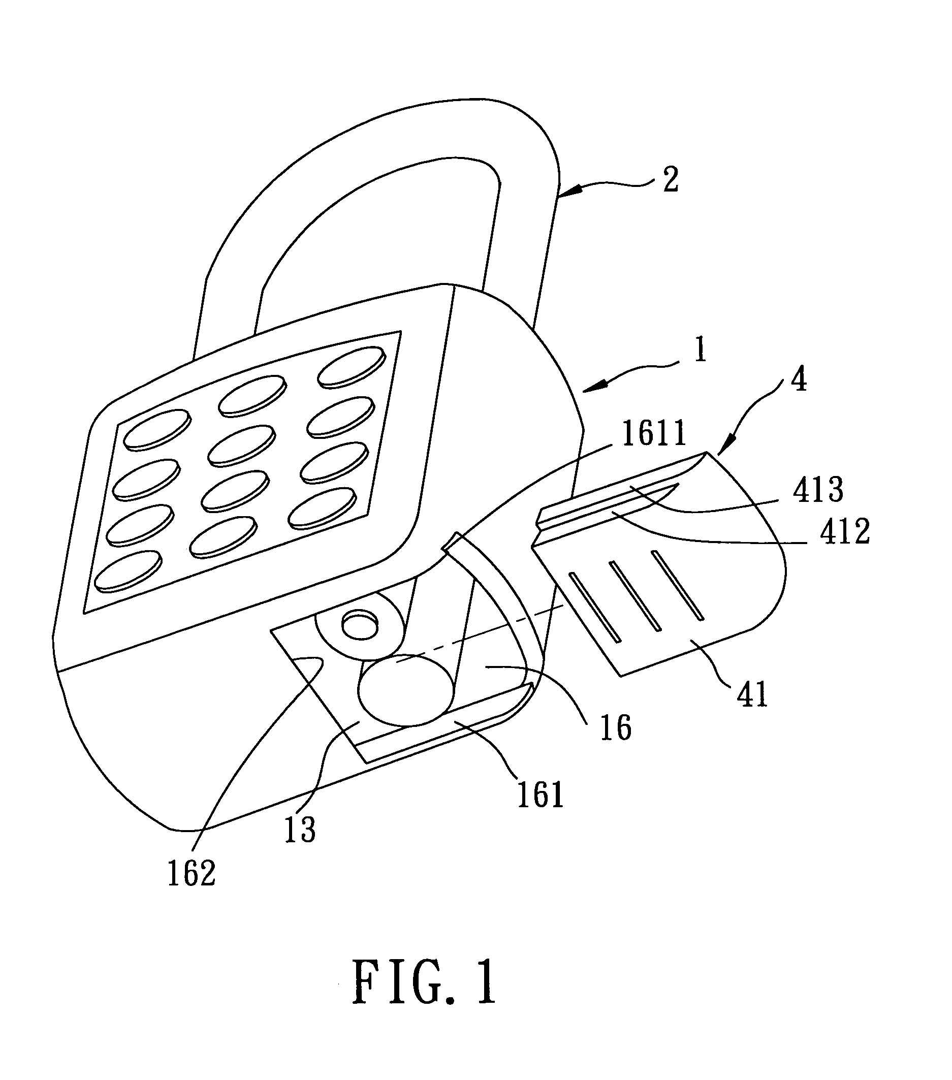
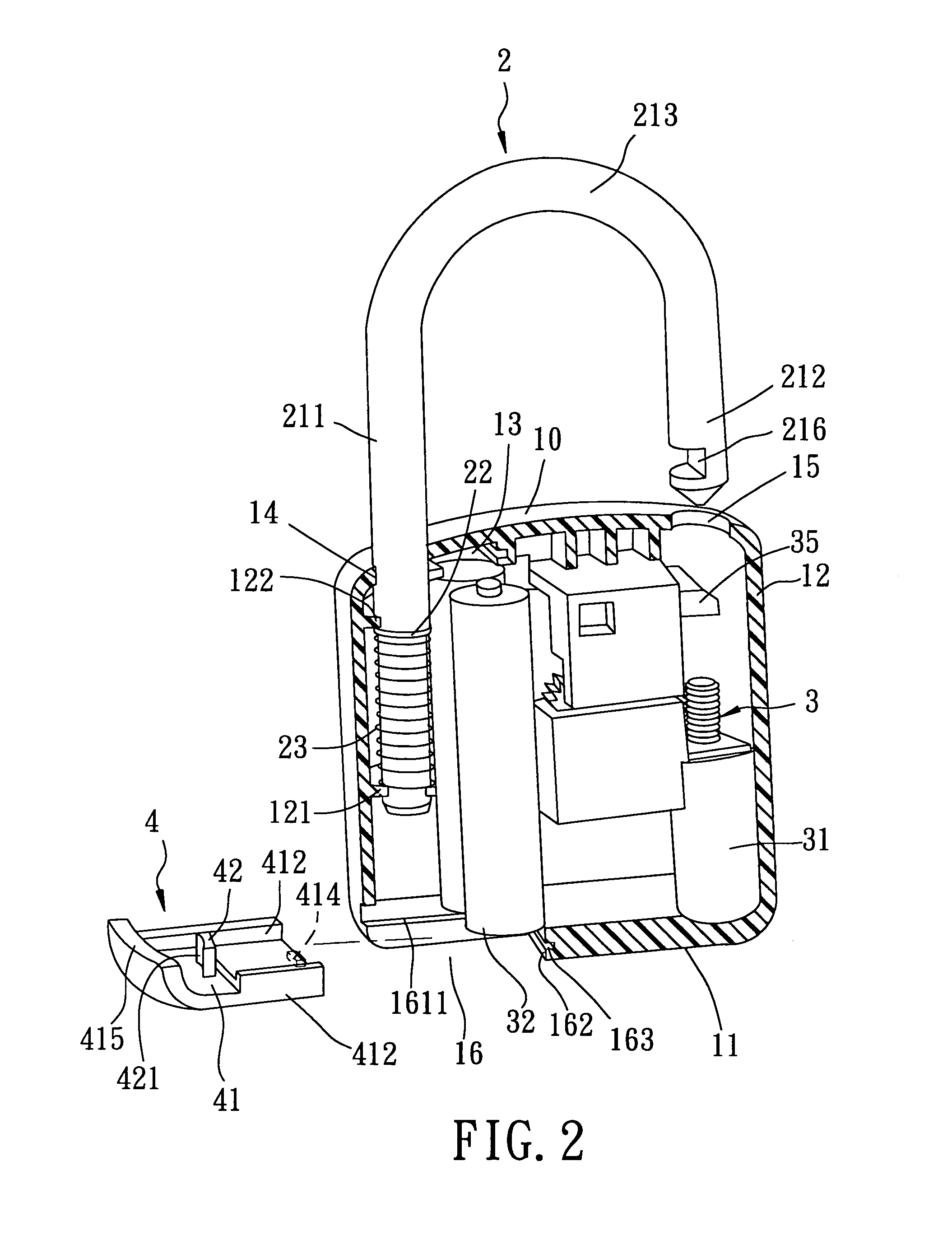
[0014]Referring to FIGS. 1 and 2, the preferred embodiment of an electric padlock according to the present invention is shown to include a lock casing 1, an inverted U-shaped shackle member 2, a latch member 35, and a battery cap member 4.

[0015]The lock casing 1 has a first end wall 10, a second end wall 11 opposite to the first end wall 10, and a surrounding wall 12 that extends between and that interconnects the first and second end walls 10, 11. The first end wall 10 is formed with first and second shackle insert holes 14, 15. The lock casing 1 further has a battery compartment 13 that is adapted for receiving a battery unit 32, and a battery access hole 16 that permits insertion of the battery unit 32 into and removal of the battery unit 32 from the battery compartment 13. The battery access hole 16 is formed in the second end wall 11, extends to the surrounding wall 12, and is defined by a pair of lateral wall portions 161 and a distal wall portion 162 that interconnects the la...


PUM


Abstract

An electric padlock includes a lock casing, a shackle member, a latch member, and a battery cap member. The lock casing is formed with a battery compartment to receive a battery unit, and a battery access hole. The shackle member extends movably into the lock casing, and is formed with a shackle groove. The latch member is received in the lock casing, and is movable to engage the shackle groove so as to lock the shackle member on the lock casing, and to disengage from the shackle groove so as to unlock the shackle member from the lock casing. The battery cap member is mounted movably on the lock casing to close the battery access hole, and is formed with a stop projection that engages the shackle member so as to inhibit opening movement of the battery cap member when the shackle member is locked on the lock casing.

Description

BACKGROUND OF THE INVENTION[0001]1. Field of the Invention[0002]The present invention relates to an electric padlock, more particularly to an electric padlock that can prevent theft of a battery unit therein.[0003]2. Description of the Related Art[0004]A conventional electric padlock includes a lock casing formed with two shackle insert holes. A shackle member has a longer leg portion that is movably disposed in one of the shackle insert holes and that is biased upwardly. A latch member is received in the lock casing, and is movable between locking and unlocking positions for engaging and disengaging a shackle groove in a shorter leg portion of the shackle member. The electric padlock further includes an electric operating unit that has a drive motor mounted in the lock casing, coupled to the latch member, and operable for moving the latch member between the locking and unlocking positions.[0005]The electric operating unit draws electric power from a battery unit that is received in...

Claims


Application Information

Patent Timeline
IPC IPC(8): E05B67/22E05B47/00E05B67/00
CPCE05B47/0012E05B67/22E05B2047/0058E05B2047/0024Y10T70/459Y10T70/461Y10T70/489Y10T70/7113Y10T70/7124
Inventor LIN, LUNG-YIN
Owner EZ TREND TECH
Why Eureka
Try Eureka