Electric Padlock

Inactive Publication Date: 2006-02-07
EZ TREND TECH
View PDF14 Cites 49 Cited by
  • Summary
  • Abstract
  • Description
  • Claims
  • Application Information

AI Technical Summary

Benefits of technology

[0013]One of the first and second leg portions of the shackle member is provided with a release-control segment adjacent to the battery access hole such that, when the shackle member is unlocked from the l

Problems solved by technology

The conventional electric padlock is disadvantageous in that, since the battery cap member can be removed regardless of whether the shackle member is locked or unlocked from the lock casing, the electric padlock can be vandalized by simply

Method used


Image

  • Electric Padlock
  • Electric Padlock
  • Electric Padlock

Examples


Embodiment Construction

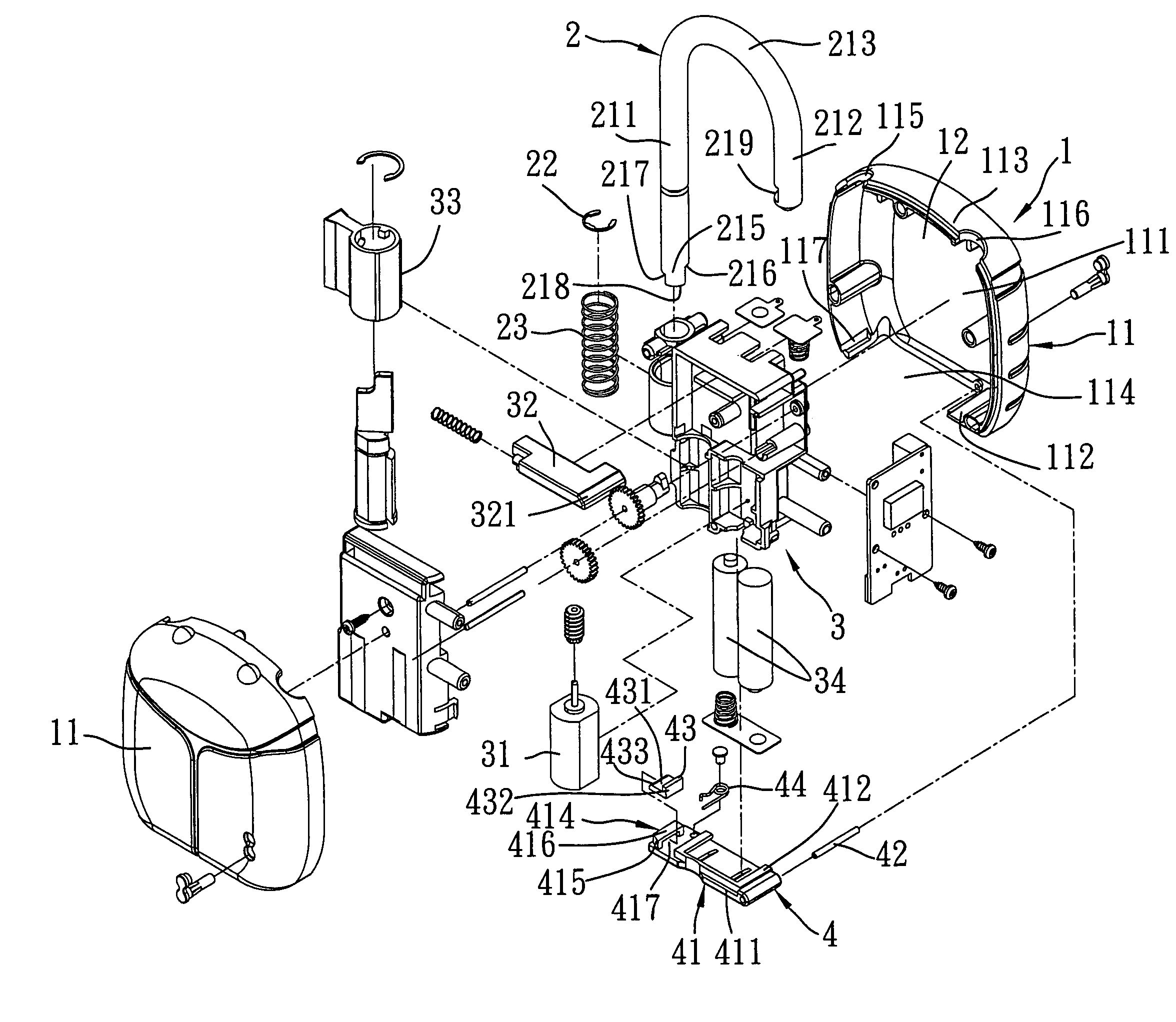
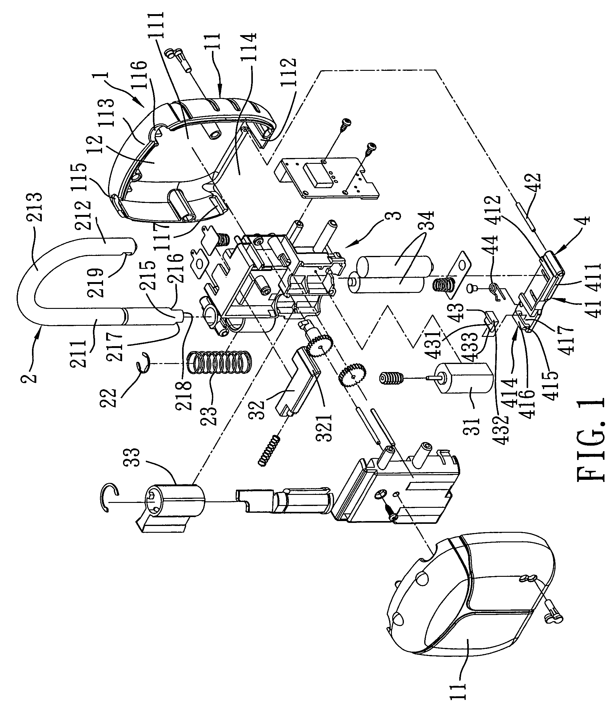
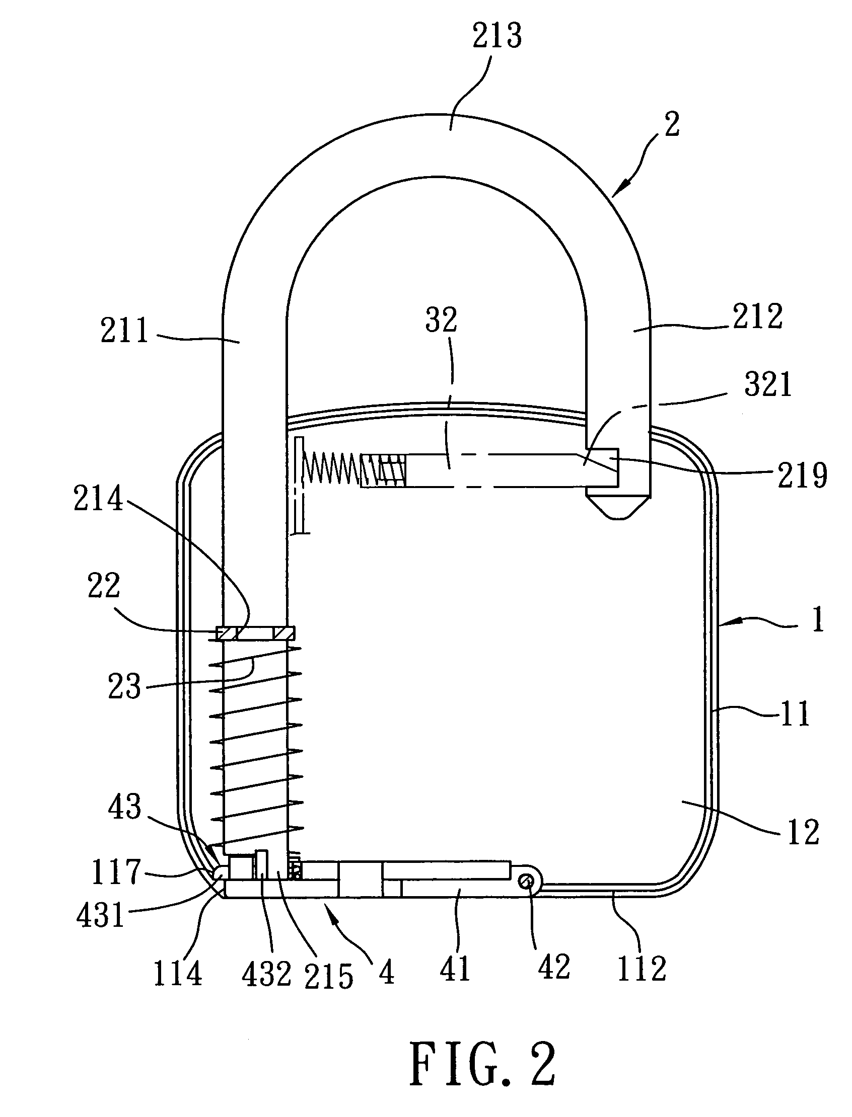
[0024]Referring to FIGS. 1 to 3, the preferred embodiment of an electric padlock according to the present invention is shown to include a lock casing 1, an inverted U-shaped shackle member 2, a latch member 32, and a battery cap unit 4.

[0025]The lock casing 1 is formed from a pair of complementary casing parts 11, and confines a receiving space 12 adapted for receiving a battery unit 34 therein. When the casing parts 11 are assembled, the lock casing 1 is configured with a first end wall 113, a second end wall 112 opposite to the first end wall 113, and a pair of side wall parts 111 that extend between and that interconnect the first and second end walls 113, 112. The first end wall 113 is formed with first and second shackle insert holes 115, 116. The second end wall 112 is formed with a battery access hole 114 that permits insertion of the battery unit 34 into and removal of the battery unit 34 from the receiving space 12. The lock casing 1 is further formed with an insert groove ...


PUM


Abstract

An electric padlock includes a lock casing, a shackle member, a latch member, and a battery cap unit. The lock casing is formed with a receiving space for receiving a battery unit, a battery access hole, and an insert groove disposed adjacent to the battery access hole. The latch member is received in the lock casing, and is movable for locking and unlocking the shackle member relative to the lock casing. The battery cap unit includes a battery cap member mounted movably on the lock casing for closing selectively the battery access hole, and a retaining member provided movably on the battery cap member to engage the insert groove when in a retaining position such that opening movement of the battery cap member can be inhibited when the shackle member is locked on the lock casing.

Description

BACKGROUND OF THE INVENTION[0001]1. Field of the Invention[0002]The present invention relates to an electric padlock, more particularly to an electric padlock that can prevent unauthorized removal of a battery unit therein.[0003]2. Description of the Related Art[0004]A conventional electric padlock includes a lock casing formed with two shackle insert holes. A shackle member has a longer leg portion that is movably disposed in one of the shackle insert holes and that is biased upwardly. A latch member is received in the lock casing, and is movable between locking and unlocking positions for engaging and disengaging a shackle groove in a shorter leg portion of the shackle member. The electric padlock further includes an electric operating unit that has a drive motor mounted in the lock casing, coupled to the latch member, and operable for moving the latch member between the locking and unlocking positions.[0005]The electric operating unit draws electric power from a battery unit that...

Claims


Application Information

Patent Timeline
IPC IPC(8): E05B67/22
CPCE05B47/0012E05B67/24E05B47/0603Y10T70/459Y10T70/461Y10T70/463Y10T70/489Y10T70/7062
Inventor CHANG, JING-CHEN
Owner EZ TREND TECH
Why Eureka
Try Eureka