System and method for dynamic codec alteration

a dynamic codec and codec technology, applied in the field of telecommunications systems, can solve the problems of inefficient utilization of system bandwidth, high bandwidth consumption, and other problems, and achieve the effects of less bandwidth-intense, high bandwidth-use coding algorithms, and high system bandwidth usag

Inactive Publication Date: 2006-04-04
SIEMENS ENTERPRISE COMM GMBH & CO KG
View PDF14 Cites 165 Cited by
  • Summary
  • Abstract
  • Description
  • Claims
  • Application Information

AI Technical Summary

Benefits of technology

[0006]These and other drawbacks in the prior art are overcome in large part by a coding algorithm policy adjustment system according to the present invention. A bandwidth adjustment server or bandwidth allocation server (BWAS) is provided which monitors system bandwidth usage, sends requests to user terminals to identify their coding capabilities, and directs each of the user terminals to adjust their coding algorithms based on system bandwidth usage. If system bandwidth usage is high, the BWAS requires the user terminals to employ a less bandwidth-intense coding algorithm; similarly, when system bandwidth usage is low, the BWAS will allow the user terminals to employ higher bandwidth-use coding algorithms.

Problems solved by technology

As a consequence, a few users who communicate using coding algorithms that result in high bandwidth consumption could use the entire network bandwidth, without even realizing bandwidth was in short supply, thereby preventing others from placing calls.
As such, system bandwidth may be inefficiently utilized and even result in denial of service to some users.
Moreover, subsequently callers with a higher QoS (quality of service) may be forced to use a less optimal codec while a preceding call with a low QoS communicates using its desired codec.
While certain data modems, such as described in U.S. Pat. No. 5,546,395, allow for dynamic bandwidth adjustment between two communicating endpoints, by way of selecting the compression rates for voice transmission and the modulation rate, such systems do not allow for broad network-based supervision of bandwidth allocation.

Method used


Image

  • System and method for dynamic codec alteration
  • System and method for dynamic codec alteration
  • System and method for dynamic codec alteration

Examples


Embodiment Construction

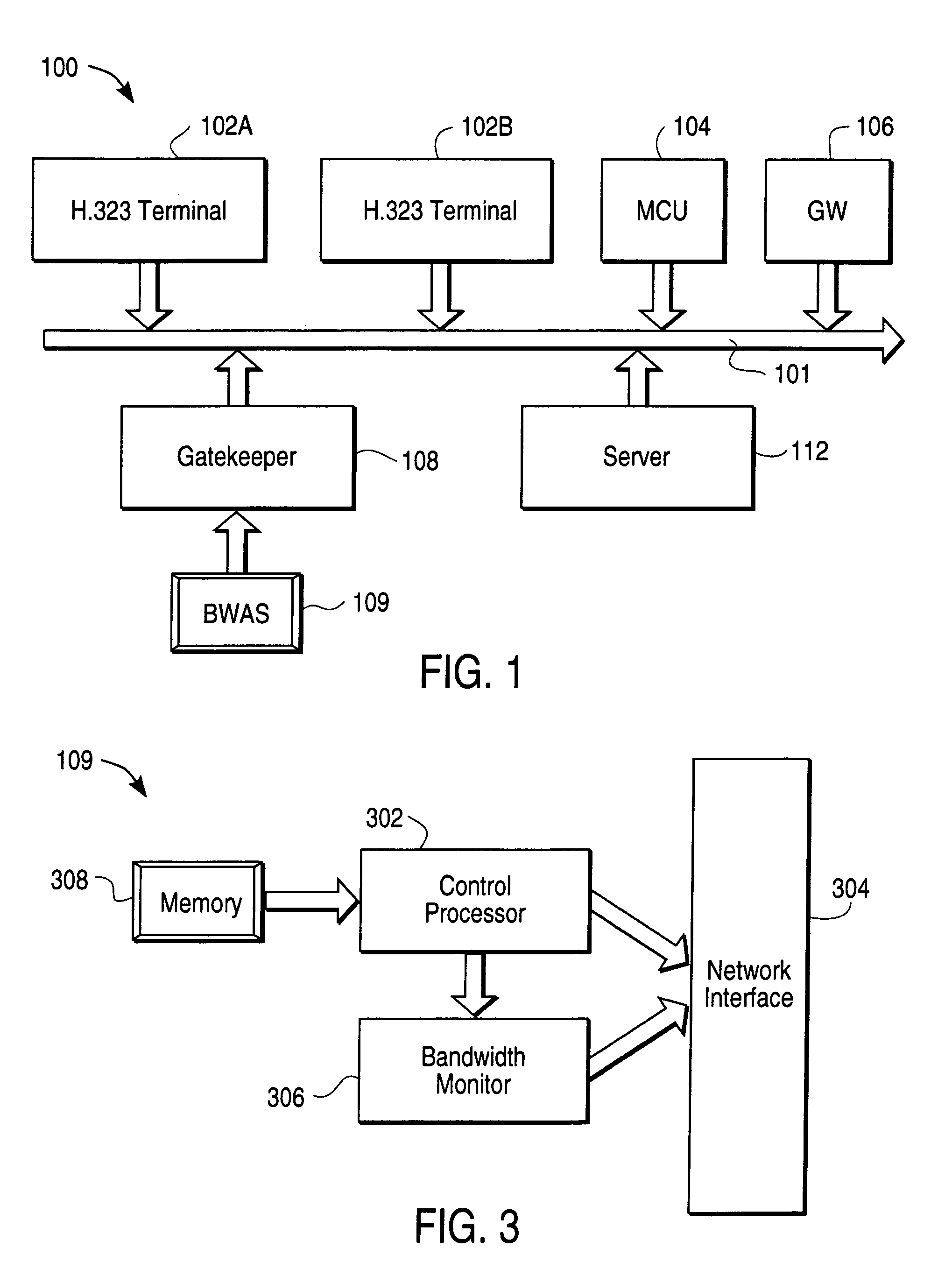
[0020]FIG. 1 is a diagram illustrating a telecommunications system 100 according to an embodiment of the present invention. In particular, the telecommunications system 100 includes a local area network (LAN) or packet network 101. Coupled to the LAN 101 may be a variety of H.323 terminals 102A, 102B, a multi-point control unit (MCU) 104, an H.323 gateway 106, an H.323 gatekeeper 108, a LAN server 112 and a plurality of other devices such as personal computers (not shown). The H.323 terminals 102A, 102B are in compliance with the H.323 standard. Thus, the H.323 terminals 102A, 102B support H.245 for negotiation of channel usage, Q.931 for call signaling and call setup, registration admission status (RAS), and RTP / RTCP for sequencing audio and video packets. The H.323 terminals 102A, 102B may further implement audio and video codecs, T.120 data conferencing protocols and MCU capabilities. Further details concerning the Recommendation H.323 may be obtained from the International Telec...


PUM


Abstract

A bandwidth adjustment server (BWAS) (109) is provided which monitors system bandwidth usage, sends requests to terminals (102A, 102B and/or 106), to identify their coding capabilities, and directs each of the terminals to adjust their coding algorithms based on system bandwidth usage. If system bandwidth usage is high, the BWAS (109) requires the terminals to employ a less bandwidth intensive coding algorithm; similarly, when system bandwidth usage is low, the BWAS (109) will allow the terminals to employ higher bandwidth use coding algorithms. Codec renegotiation may be initiated if there is a disparity between the bandwidth allocated to new connections versus ongoing connections or an increase in data traffic.

Description

CROSS REFERENCE TO RELATED APPLICATION[0001]The present application is a continuation-in-part of U.S. patent application Ser. No. 09 / 238,671, entitled “System and Method for Coding Algorithm Policy Adjustment in Telephony-Over-LAN Networks” (with inventors Shmuel Shaffer, William J. Beyda and Uwe Wrede), filed Jan. 26, 1999, now U.S. Pat. No. 6,757,277.BACKGROUND OF THE INVENTION[0002]The present invention relates to telecommunications systems, and in particular, to an improved telephony-over-LAN (local area network) system.[0003]Modern telephony-over-LAN (ToL) systems allow each endpoint (e.g., client, gateway) to choose a default hierarchy of coding algorithms. For example, an endpoint might be configured to first try using adaptive pulse code modulation (ADPCM), next G.723, then GSM, etc., until a common codec supported by both the calling and called endpoints is found.[0004]However, the endpoints or clients typically have static configurations of preferred codecs. As a consequen...

Claims


Application Information

Patent Timeline
Patent Type & Authority Patents(United States)
IPC IPC(8): H04L12/56H04L1/00H04L5/14H04L29/06H04L29/08H04M7/00
CPCH04L1/0014H04L5/1438H04L29/06H04L47/10H04M7/0003H04L65/1009H04L65/1083H04L65/80H04L67/303H04L67/325H04L67/14H04L1/0025H04L69/329H04L29/06027H04L69/24H04M7/126H04L65/1106H04L67/62H04L65/756H04L9/40H04L65/1101
Inventor SHAFFER, SHMUELBEYDA, WILLIAM JOSEPH
Owner SIEMENS ENTERPRISE COMM GMBH & CO KG
Why Eureka
Try Eureka