
Micromechanical gyroscope with double-sensitive mode
A micro-machined gyroscope, sensitive mode technology, applied in the direction of the gyro effect for speed measurement, gyroscope/steering sensing equipment, measurement devices, etc. Resolution, low gain of gyro system, etc.
- Summary
- Abstract
- Description
- Claims
- Application Information
AI Technical Summary
Problems solved by technology
Method used
Image

Examples
Embodiment Construction
[0020] The present invention is described in more detail below in conjunction with accompanying drawing example:
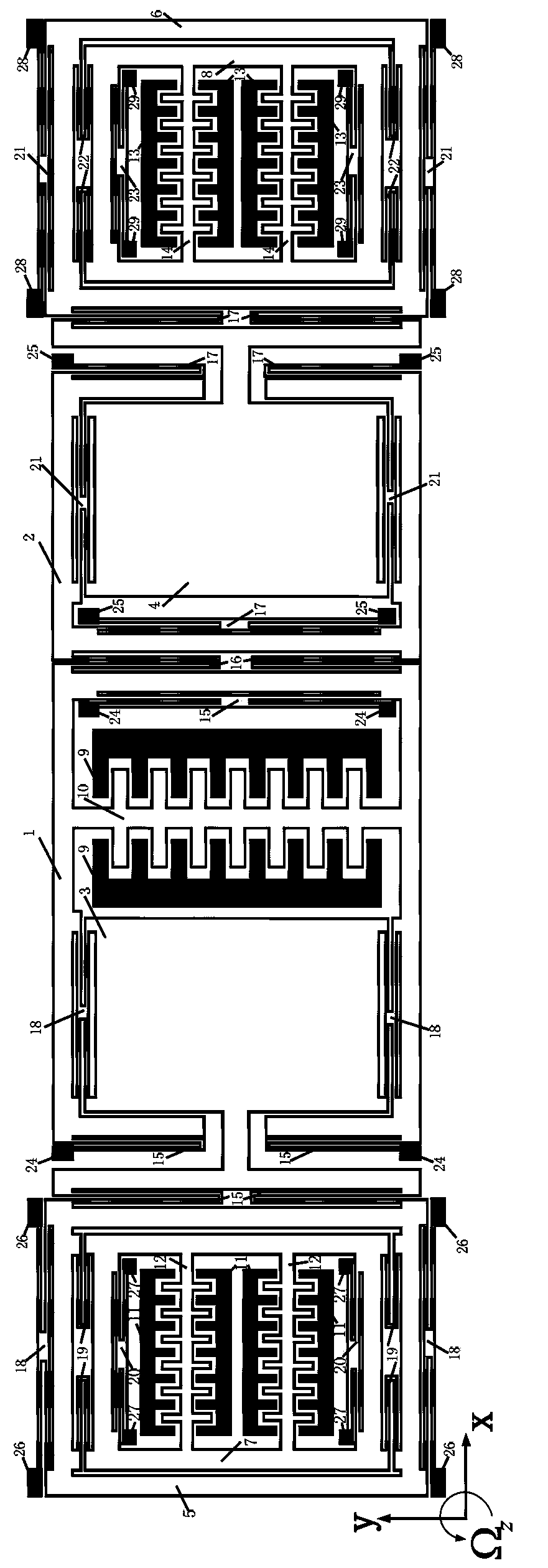
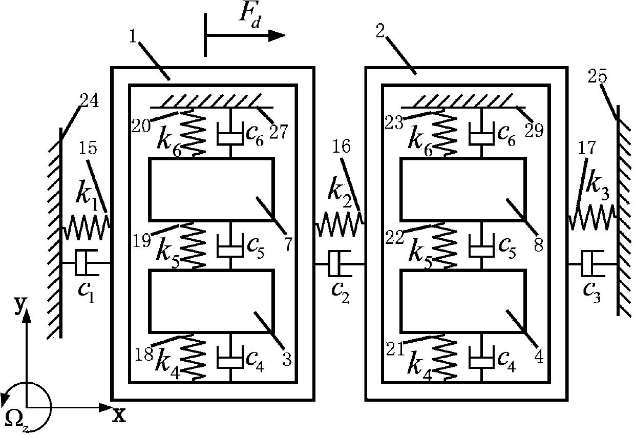
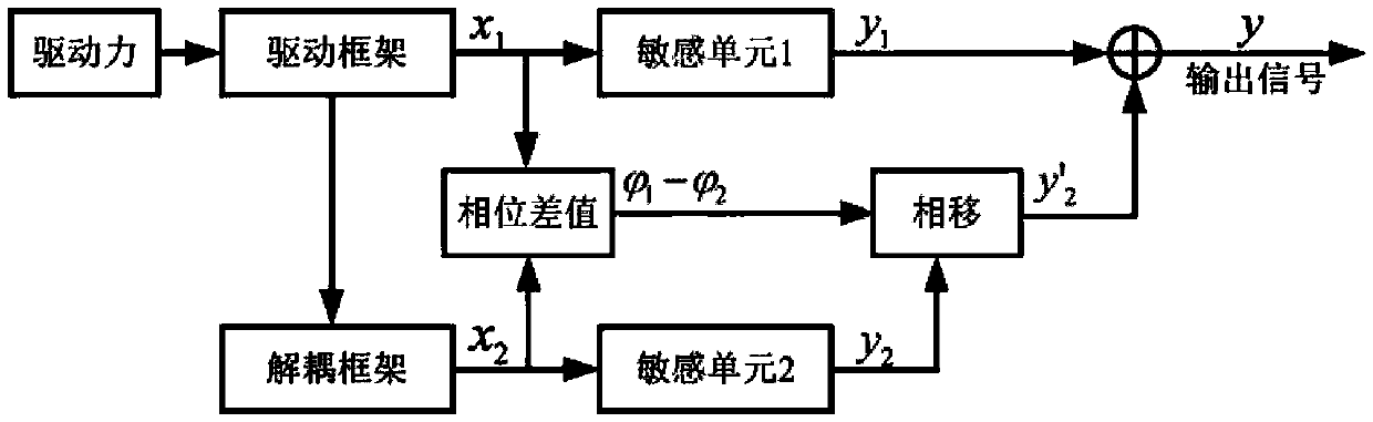
[0021] to combine figure 1 The structure of the present invention mainly includes a drive frame 1, a decoupling frame 2, a static drive comb 9 and a dynamic drive comb 10, a first detection mass 3 and a second detection mass 4, a first detection frame 5 and a second detection mass. The frame 6 , the first sensitive mass 7 and the second sensitive mass 8 , the first static sensitive comb 11 and the first dynamic sensitive comb 12 , the second static sensitive comb 13 and the second dynamic sensitive comb 14 . The driving unit consisting of the static driving comb 9 and the dynamic driving comb 10 is arranged on the driving frame 1, the driving frame 1 is connected with the anchor point one 24 through the spring beam one 15, and the driving frame 1 and the decoupling frame 2 are connected through the spring beam two 16 is connected, and the decoupling frame 2 and t...
PUM
 Abstract
Description
Claims
Application Information