Eureka AIR delivers breakthrough ideas for toughest innovation challenges, trusted by R&D personnel around the world.

A micromechanical gyroscope with dual sensitive modes

A micro-machined gyroscope, sensitive modal technology, applied in the direction of the gyro effect for speed measurement, gyroscope/steering sensing equipment, measurement devices, etc., can solve the problem of low gain of the gyro system, affecting the sensitivity or resolution of the micro-machine gyroscope, and many restrictions. Degree of freedom micromachined gyroscope application field and other issues

Active Publication Date: 2015-10-21
江苏和正特种装备有限公司
View PDF15 Cites 0 Cited by
  • Summary
  • Abstract
  • Description
  • Claims
  • Application Information

AI Technical Summary

Problems solved by technology

For example, the patent application number is 201210124320.9, and the micromechanical gyroscope disclosed in the patent document named "a four-degree-of-freedom micromechanical gyroscope" adopts a complete two-degree-of-freedom vibration structure in both the driving mode and the sensitive mode. The sensitive mode is connected together through the decoupling frame and the detection mass. Although the micro-mechanical gyroscope ensures the stability of the driving mode and the sensitive mode, the gain of the gyro system is low, which affects the sensitivity or resolution of the micro-mechanical gyroscope. Rate
Therefore, how to improve the gain of the gyro system while ensuring the bandwidth of the stability of the gyro system is an important problem in the multi-degree-of-freedom micro-mechanical gyroscope, which also limits the application field of the multi-degree-of-freedom micro-mechanical gyroscope.

Method used


Image

  • A micromechanical gyroscope with dual sensitive modes
  • A micromechanical gyroscope with dual sensitive modes
  • A micromechanical gyroscope with dual sensitive modes

Examples


Embodiment Construction

[0020] The present invention is described in more detail below in conjunction with accompanying drawing example:

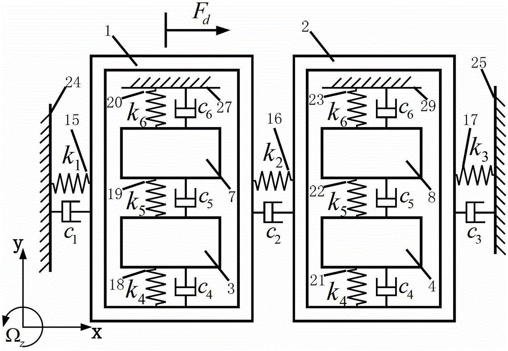
[0021] combine figure 1 The structure of the present invention mainly includes a drive frame 1, a decoupling frame 2, a static drive comb 9 and a dynamic drive comb 10, a first detection mass 3 and a second detection mass 4, a first detection frame 5 and a second detection mass. The frame 6 , the first sensitive mass 7 and the second sensitive mass 8 , the first static sensitive comb 11 and the first dynamic sensitive comb 12 , the second static sensitive comb 13 and the second dynamic sensitive comb 14 . The driving unit consisting of the static driving comb 9 and the dynamic driving comb 10 is arranged on the driving frame 1, the driving frame 1 is connected with the anchor point one 24 through the spring beam one 15, and the driving frame 1 and the decoupling frame 2 are connected through the spring beam two 16 is connected, and the decoupling frame 2 and the ...


PUM


Abstract

The invention designs a novel micromechanical gyroscope with a double-sensitive mode, which is mainly used for improving the gains of a micromechanical gyroscope so as to improve the sensitivity. The micromechanical gyroscope structure designed by the invention applies complete two-degree-of-freedom vibration structures to a driving mode and a sensitive mode; a double-sensitive mode structure is adopted, namely the sensitive mode has the two complete two-degree-of-freedom vibration structures which are connected with a driving framework and a decoupling framework of the driving mode through detection mass blocks respectively so as to realize the decoupling of the double-sensitive mode and the driving mode. The complete two-degree-of-freedom vibration structures can be used for increasing 3dB bandwidths of the driving mode and the sensitive mode, so that the stability of a gyroscope system is improved; the double-sensitive mode can improve the whole output gains and the sensitivity of the gyroscope system. The novel micromechanical gyroscope provided by the invention has the advantages of good stability, interference resistance and high sensitivity; vacuum encapsulation is avoided; the novel micromechanical gyroscope is good for extensive practical application.

Description

technical field [0001] The invention relates to a micromechanical gyroscope structure with dual sensitive modes. Background technique [0002] The development and research of micro-mechanical gyroscopes began in the late 1980s. In the past 20 years, research institutions in many countries have conducted in-depth research on micro-mechanical gyroscopes and achieved certain research results. Now, micromechanical gyroscopes have been applied to the fields of electronics, automobile industry, and intelligent navigation systems, and with the development of time, their scope of application has continued to expand. At present, the research of MEMS is mainly focused on the design of new device structures, how to design a good MEMS structure to improve the performance of MEMS. The structural design of the micro-mechanical gyroscope is mainly divided into two-degree-of-freedom structure and multi-degree-of-freedom structure: the driving mode and the sensitive mode of the two-degree-o...

Claims


Application Information

Patent Timeline
Patent Type & Authority Patents(China)
IPC IPC(8): G01C19/5733
Inventor 王伟吕晓永李欣宋鸿儒韩莉莉赵清杨博范岳朱玮李强
Owner 江苏和正特种装备有限公司
Why Eureka
Eureka Blog
Learn More