
Improved Control of Directional Antennas for Wireless Links

An antenna and radio technology used in the field of evaluating the transmit and receive antenna patterns of directional payload antennas, which can solve the problems of communication system performance deterioration, inability to align and adapt antennas, etc.

Active Publication Date: 2019-11-12
TELEFON AB LM ERICSSON (PUBL)
View PDF5 Cites 0 Cited by
  • Summary
  • Abstract
  • Description
  • Claims
  • Application Information

AI Technical Summary

Problems solved by technology

These events may cause refracted or reflected radio signals to change direction, and thus the performance of communication systems using NLOS channels may deteriorate
[0012] Therefore, another problem is that NLOS radio links cannot be expected to exhibit the same degree of stability with respect to propagation conditions as conventional LOS microwave links, where antenna alignment is usually only during the deployment of the radio link Finished at once
the existing NLOS radio link infrastructure cannot and will not be able to adapt its antenna alignment to changing propagation conditions and therefore may suffer performance degradation if the surrounding environment changes

Method used


Image

  • Improved Control of Directional Antennas for Wireless Links
  • Improved Control of Directional Antennas for Wireless Links
  • Improved Control of Directional Antennas for Wireless Links

Examples


Embodiment Construction

[0071] Aspects of the present disclosure will be described more fully hereinafter with reference to the accompanying drawings. However, the apparatus and methods disclosed herein may be implemented in many different forms and should not be construed as limited to the embodiments and aspects set forth herein. Like reference numerals refer to like elements throughout the drawings.

[0072] The terms used herein are for the purpose of describing specific aspects of the present disclosure only, and are not intended to limit the present invention. As used herein, the singular forms "a", "an" and "the" are intended to also include the plural forms unless the context clearly dictates otherwise.

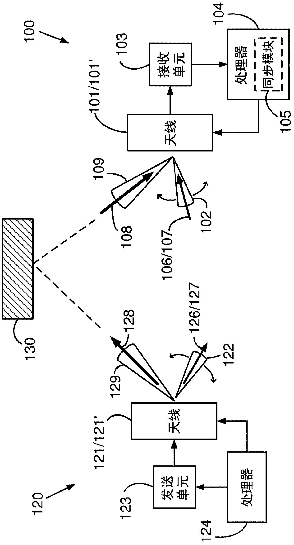
[0073] figure 1 Shown is a radio receiver 100 and a radio transmitter 120 arranged to exchange payload signals 128 , 108 and probe signals 126 , 106 via indirect propagation paths, possibly through objects 130 in the environment. This indirect propagation path differs from the line-of-si...


PUM


Abstract

The present disclosure relates to a radio receiver, a radio transmitter, and methods for evaluating receive and transmit antenna patterns of directive payload antennas. The method for evaluating receive antenna patterns of a directive payload antenna comprises the step of steering a probing signal receive pattern of a steerable receive pattern antenna according to a pre-determined sequence of probing signal receive patterns, and receiving a probing signal via the steerable receive pattern antenna, as well as determining a probing signal quality value from the received probing signal as a function of the pre-determined sequence of probing signal receive patterns.

Description

technical field [0001] The present disclosure relates to radio transmitters, radio receivers, and methods for evaluating transmit and receive antenna patterns of directional loading antennas. Background technique [0002] A point-to-point radio link is a system of wireless transceivers used for point-to-point radio communication between two fixed stations. Radio links are typically used for backhaul in cellular networks, ie for connecting network elements such as base stations to the core network. [0003] Traditional radio links are generally based on microwave transmission and are deployed as a rule in line-of-sight LOS conditions. The meaning of the LOS condition is that there is a clear line of sight between two fixed transceiver sites, so that the propagation path of the wireless signal propagation is not blocked or blocked by obstacles. The opposite situation, ie, when the transmission path is shadowed or blocked and the radio propagation is via refraction or reflect...

Claims


Application Information

Patent Timeline
Patent Type & Authority Patents(China)
IPC IPC(8): H04B7/06H04B7/08H04W16/28
CPCH04B7/0617H04B7/0825H04B7/084H04B7/086H04B17/21H01Q3/02H04W16/28H04W52/241
Inventor 本特·埃里克·奥尔森克里斯蒂娜·拉森马特斯·里德斯特罗姆乔纳斯·汉塞德
Owner TELEFON AB LM ERICSSON (PUBL)
Learn More