
Coaxial communication active tap device and distribution system
a tap device and coaxial communication technology, applied in the direction of two-way working systems, line-transmission details, television systems, etc., can solve the problems of a single power source providing a much larger distribution network and/or a lower overall power consumption, and achieve the effect of reducing overall power consumption, and reducing the number of directional couplers
- Summary
- Abstract
- Description
- Claims
- Application Information
AI Technical Summary
Benefits of technology
Problems solved by technology
Method used
Image

Examples
Embodiment Construction
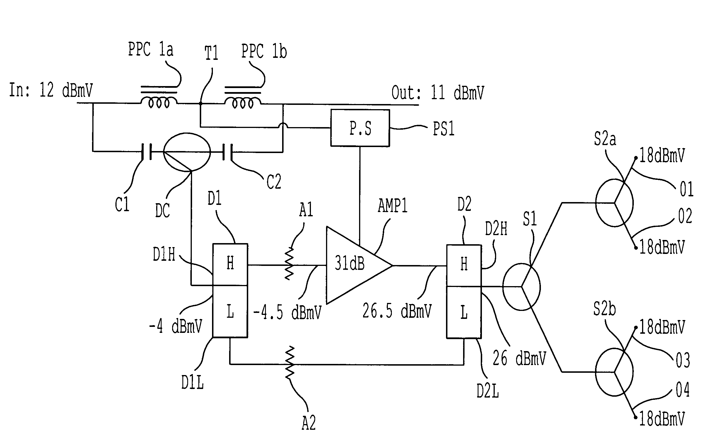
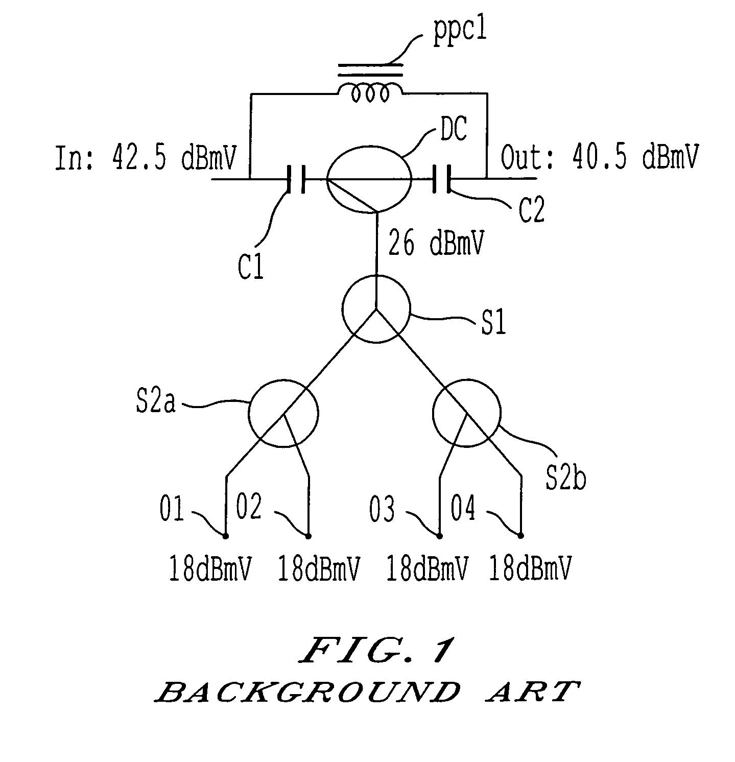
[0037]FIG. 5 shows a block diagram of an embodiment of the present invention which corresponds in function but not in operation with the conventional passive tap block diagram of FIG. 1. Here an input value of 12 dBmV is presented to a parallel circuit comprising a first power passing choke PPC1A connected to a second power passing choke PPC1B. An output tap T1 is placed between the first and second power passing chokes (PPC1A and PPC1B). Signal is passed from the output tap T1 to a power supply PS1. The output of the power supply PS1 is then fed to an amplifier AMP1. In parallel to the two power passing chokes (PPC1A and PPC1B) is a circuit, comprising: a first capacitor C1, a directional coupler DC, and second capacitor C2. The output of the directional coupler DC is fed to the combined port of a first diplex filter D1. The output of the first high-pass filter D1H is fed to the amplifier AMP1 via a first attenuator A1.
[0038]The output of the amplifier is then fed to a second high ...
PUM
 Abstract
Description
Claims
Application Information