Window air conditioner unit mounting system

a technology for mounting systems and windows, applied in ventilation systems, lighting and heating apparatuses, heating types, etc., to achieve the effects of low manufacturing cost, convenient and efficient manufacturing and marketing, and durable and reliable construction

Inactive Publication Date: 2013-11-19
PETERSON ANDREW
View PDF23 Cites 49 Cited by
  • Summary
  • Abstract
  • Description
  • Claims
  • Application Information

AI Technical Summary

Benefits of technology

[0035]It is therefore an object of the present invention to provide a new and improved window air conditioner unit mounting system which has all of the advantages of the prior art window mounts and none of the disadvantages.
[0036]It is another object of the present invention to provide a new and improved window air conditioner unit mounting system which may be easily and efficiently manufactured and marketed.
[0037]It is further object of the present invention to provide a new and improved window air conditioner unit mounting system which is of durable and reliable constructions.
[0038]An even further object of the present invention is to provide a new and improved window air conditioner unit mounting system which is susceptible of a low cost of manufacture with regard to both materials and labor, and which accordingly is then susceptible of low prices of sale to the consuming public, thereby making such window air conditioner unit mounting system economically available to the buying public.

Problems solved by technology

While the prior art devices fulfill their respective, particular objectives and requirements, the prior art does not describe window air conditioner unit mounting system that allows an improved way to mount a window air conditioner unit.

Method used


Image

  • Window air conditioner unit mounting system
  • Window air conditioner unit mounting system
  • Window air conditioner unit mounting system

Examples


Embodiment Construction

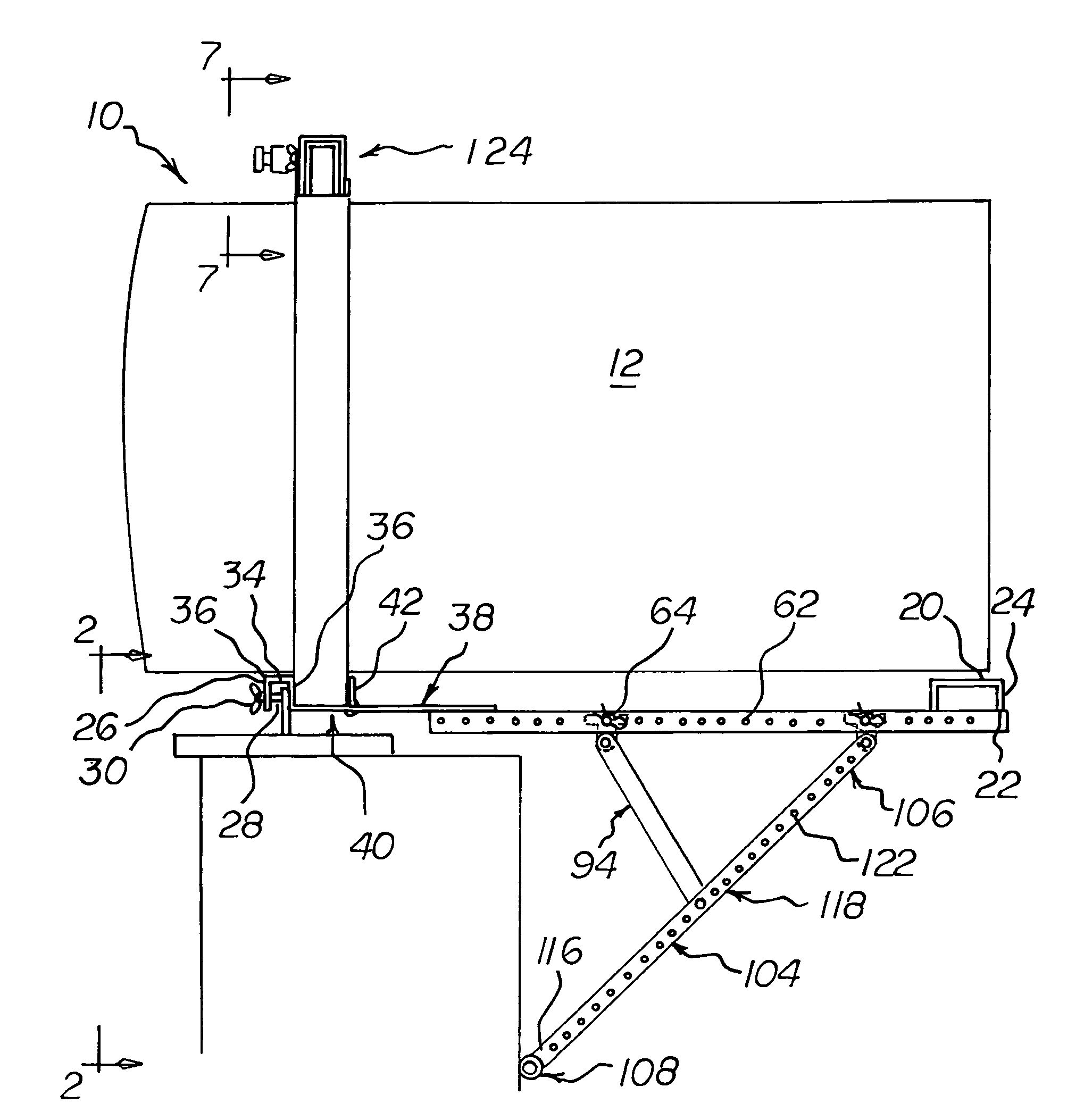
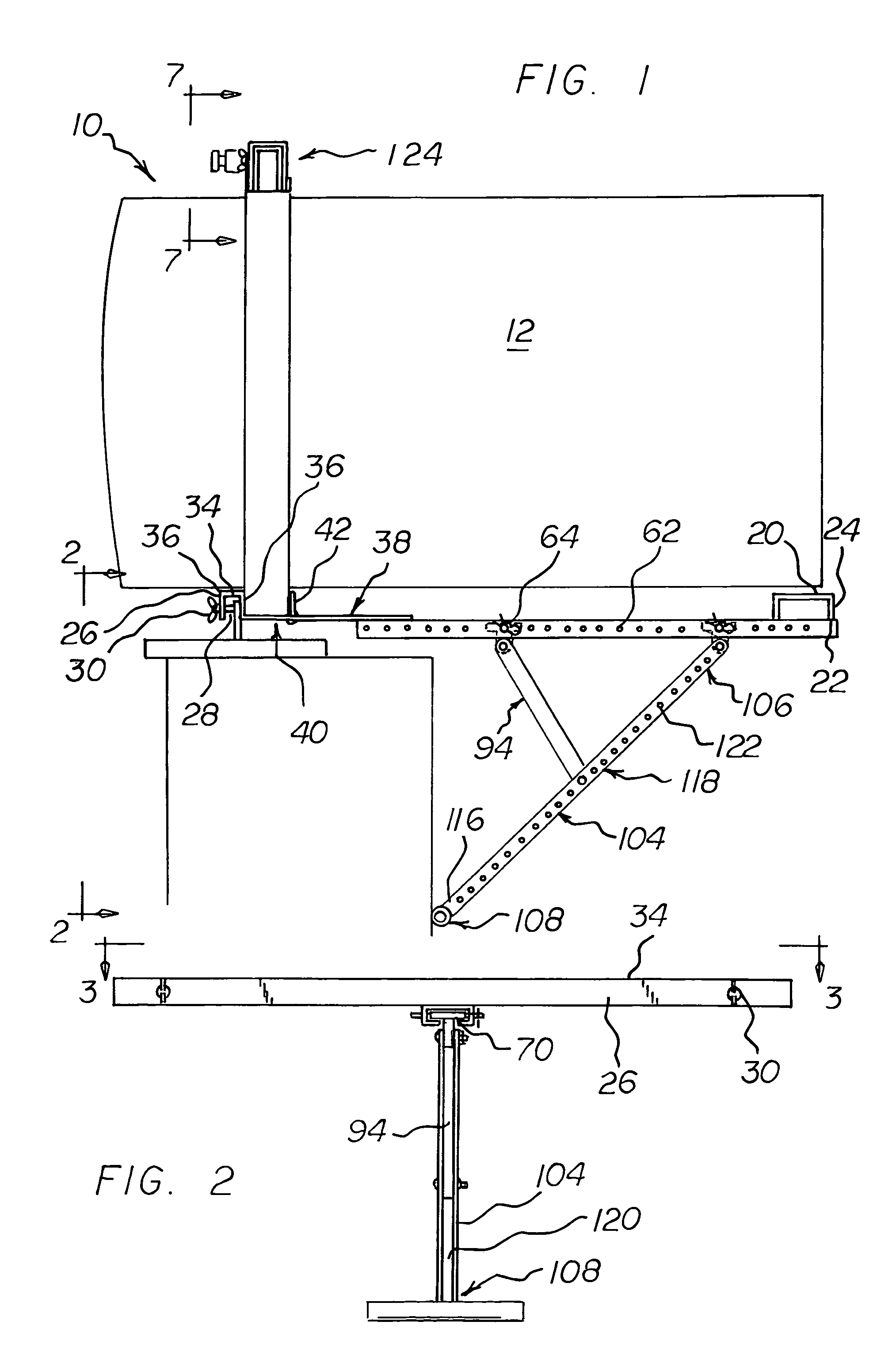
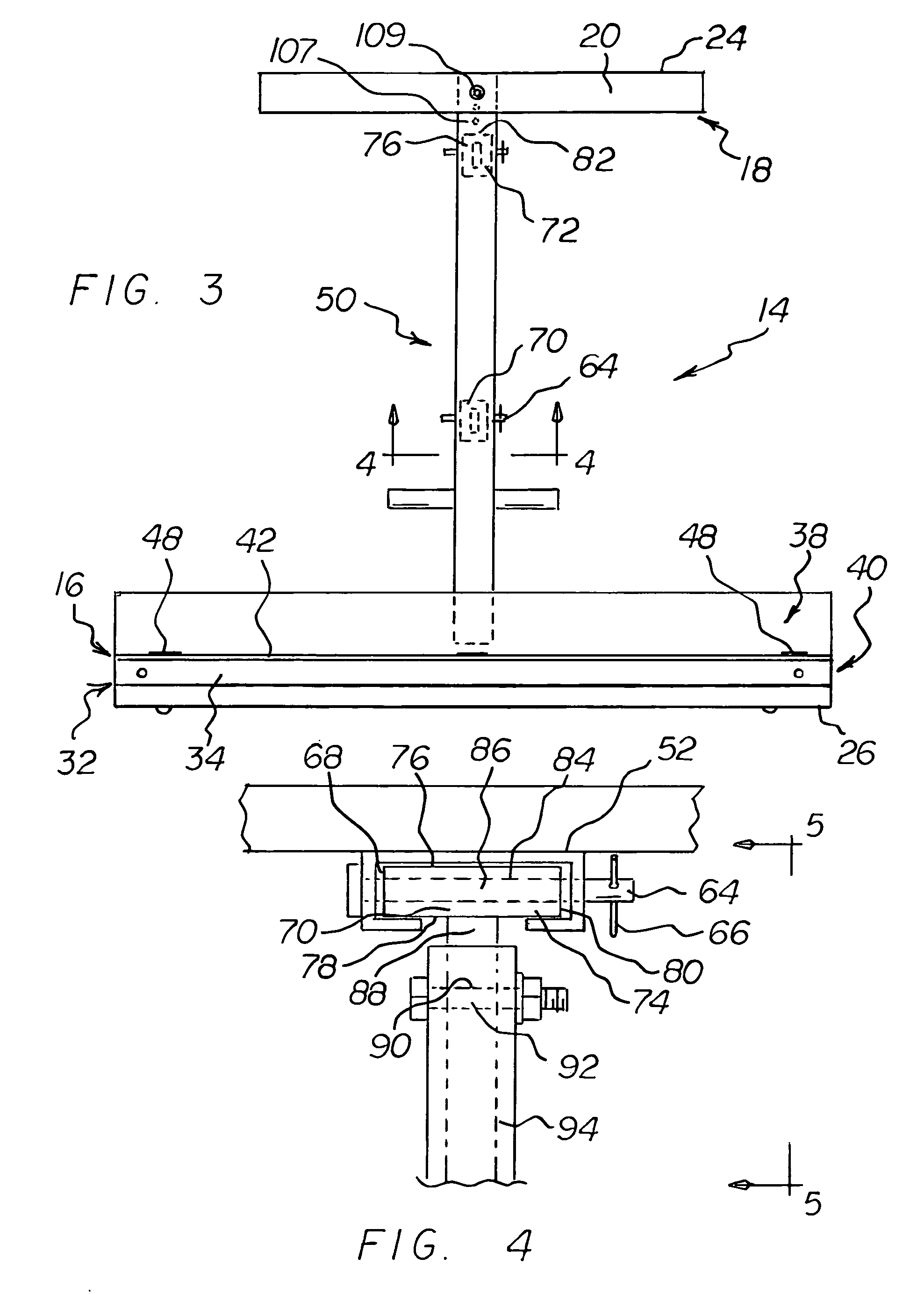
[0053]With reference now to the drawings, and in particular to FIG. 1 thereof, the preferred embodiment of the new and improved window air conditioner unit mounting system embodying the principles and concepts of the present invention and generally designated by the reference numeral 10 will be described.

[0054]The present invention, the window air conditioner unit mounting system 10 is comprised of a plurality of components. Such components in their broadest context include a base subassembly, and an upper cross member. Such components are individually configured and correlated with respect to each other so as to attain the desired objective.

[0055]The present invention, a window air conditioning unit mounting system 10 is comprised of a plurality of components, such components in their broadest context include a base subassembly, and an upper cross member. Such components are individually configured and correlated with respect to each other so as to attain the desired objective. The...


PUM


Abstract

A window air conditioning mounting system comprising a base subassembly having generally I-shaped configuration. There is also a shackle being coupled to the base subassembly. There is a strut having a generally T-shaped configuration coupled to the shackle and to the base subassembly. Lastly there is an upper cross member comprising a pair of generally C-shaped components. The components slidably receiving each other.

Description

RULE 1.78(F)(1) DISCLOSURE[0001]The Applicant has not submitted a related pending or patented non-provisional application within two months of the filing date of this present application. The invention is made by a single inventor, so there are no other inventors to be disclosed. This application is not under assignment to any other person or entity at this time.BACKGROUND OF THE INVENTION[0002]1. Field of the Invention[0003]The present invention relates to a window air conditioner unit mounting system and more particularly pertains to an improved way to mount a window air conditioner unit.[0004]2. Description of the Prior Art[0005]The use of window mounts is known in the prior art. More specifically, window mounts previously devised and utilized for the purpose of affixing an air conditioning unit to a window opening are known to consist basically of familiar, expected, and obvious structural configurations, notwithstanding the myriad of designs encompassed by the crowded prior art...

Claims


Application Information

Patent Timeline
Patent Type & Authority Patents(United States)
IPC IPC(8): A47F5/00
CPCF24F13/32F24F1/027
Inventor PETERSON, ANDREW
Owner PETERSON ANDREW
Why Eureka
Try Eureka