Skeletal implant

a technology of skeletal implants and skeletal bones, applied in the field of skeletal implants, can solve problems such as the risk of dystrophy or rupture of this other elemen

Inactive Publication Date: 2005-03-10
FRED ZACOUTO
View PDF30 Cites 170 Cited by
  • Summary
  • Abstract
  • Description
  • Claims
  • Application Information

AI Technical Summary

Benefits of technology

[0010] The object of the invention is, among other things, to eliminate these drawbacks.

Problems solved by technology

As regards the articulated implant itself, a completely rigid structure fully transmits the shocks and vibrations to the other element of the joint, resulting in a risk of dystrophy or rupture of this other element.

Method used


Image

  • Skeletal implant
  • Skeletal implant
  • Skeletal implant

Examples


second embodiment

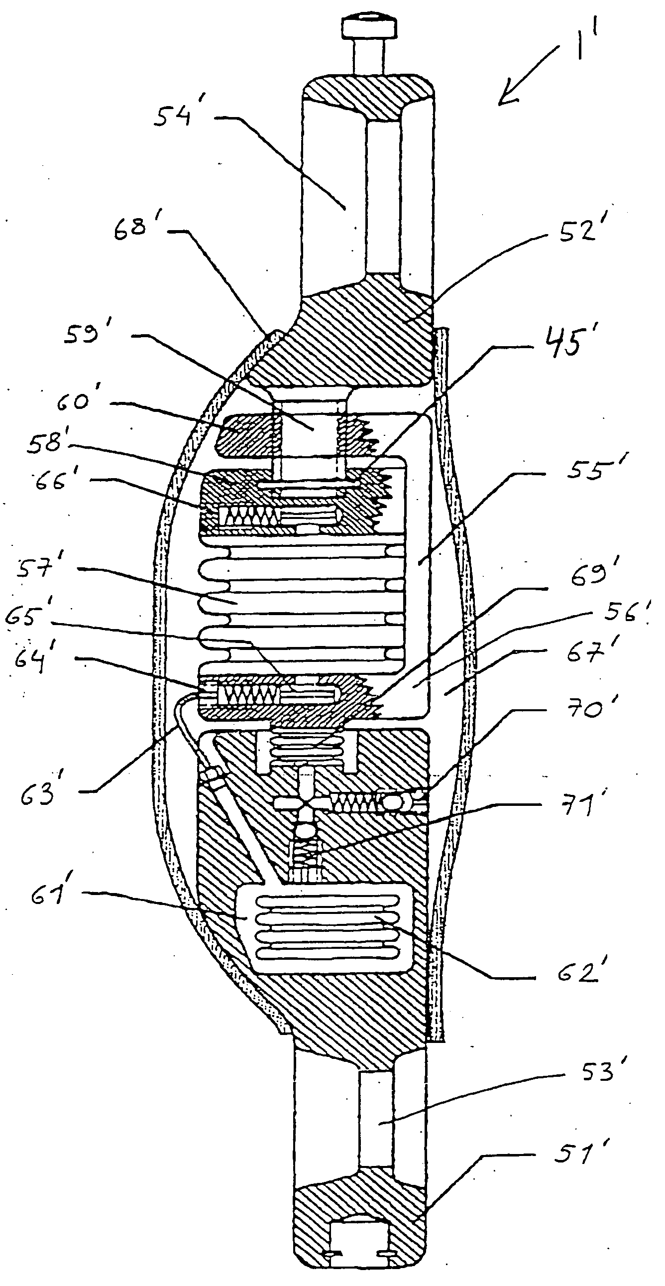
[0322] An implant according to this second embodiment could therefore be used alone, while retaining the differential pressure regulation function.

[0323] Various implantations other than that represented and described in reference to FIG. 13 can be envisaged for the implants just described.

[0324]FIG. 23 shows a bone graft 330 disposed between two vertebrae 331. Two implants 305 such as those in FIGS. 14 and 15 have been placed in the graft, symmetrically relative to the median plane of the patient's body. The interconnections between the implants and the functional principles are the same as those described in reference to FIGS. 14 through 17.

[0325]FIG. 24 shows a single implant 332 as described in reference to FIGS. 18 through 22, implanted in a graft 333, which is itself disposed between two vertebrae 334. A solution of this type ensures good performance with regard to lateral as well as frontal flexions.

[0326] Articulated implants embodied according to the invention will now b...

third embodiment

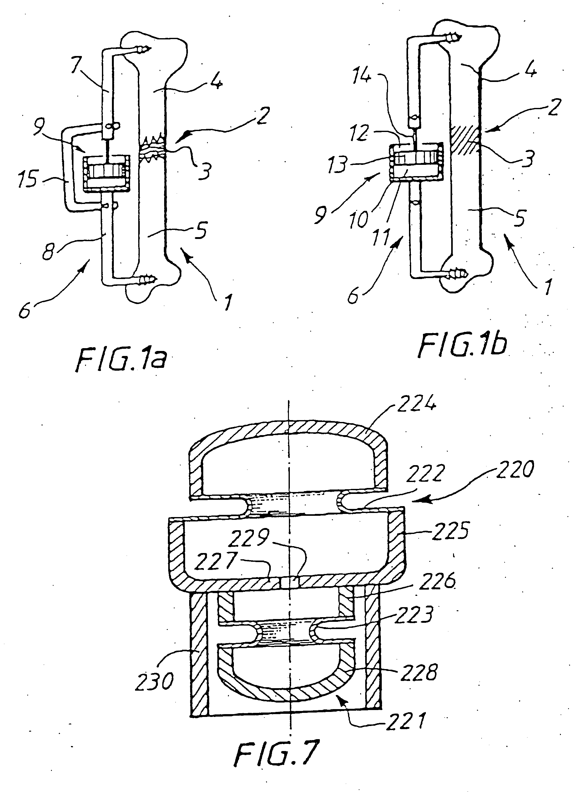
[0448] In a third embodiment, by contrast, the movable element is allowed to exert a permanent force, preferably constant or possibly progressively variable, between the two ends and thus the two portions or elements of the skeleton, with an intensity of force which is insufficient to provoke an abrupt modification of dimension and an attack on the tissue opposing this dimensional variation, but which is sufficient to provoke, as is known per se in the field of surgery, a slow deformation and an adaptation of the various tissues until the desired corrected position is reached.

[0449] Such a procedure is particularly suitable for correction of scoliosis or kyphoscoliosis.

[0450] When a force is exerted between two skeletal elements by means of an implant according to the invention, this force can advantageously be from a few daN to 25 or 30 daN.

[0451] The device can advantageously include force or pressure sensors for limiting or regulating the force to be exerted. Such miniaturized ...


PUM

PropertyMeasurementUnit
forceaaaaaaaaaa
forceaaaaaaaaaa
volumeaaaaaaaaaa

Abstract

Skeletal implant of the type to be used to connect at least two elements of a skeleton. The skeletal implant includes a first part adapted to be connected to at least one of the at least two elements of the skeleton. A second part is adapted to be connected to another of the at least two elements of the skeleton. A variable volume element is adapted to move the first and second parts with respect to each other. A high-pressure chamber supplies fluid to the variable volume element. A low-pressure chamber receives fluid from the variable volume element. A recharging variable volume element is adapted to communicate with the high-pressure chamber and the low-pressure chamber. The recharging variable volume element is responsive to displacements of corporal parts of a user and recharges the high-pressure chamber with fluid. This Abstract is not intended to define the invention disclosed in the specification, nor intended to limit the scope of the invention in any way.

Description

RELATED APPLICATION [0001] The present application is a continuation of U.S. application Ser. No. 10 / 040,029, filed Jan. 9, 2002, which is a continuation of U.S. application Ser. No. 09 / 200,855, filed Nov. 30, 1998, the disclosures of each of these documents is expressly incorporated by reference herein in their entireties. Application Ser. No. 09 / 200,855 is a continuation-in-part of application Ser. No. 08 / 897,673, filed on Jul. 21, 1997, now abandoned, the priority of which is claimed under 35 USC 120 and the disclosure of which is incorporated by reference thereto in its entirety. Further, the present application claims priority under 35 U.S.C. § 119 of French Patent Application No. 9609157 filed on Jul. 22, 1996 and French Patent Application No. 9805549 filed on Apr. 30, 1998, the disclosures of which are hereby incorporated by reference thereto in their entireties.BACKGROUND OF THE INVENTION [0002] 1. Field of the Invention [0003] The present invention relates to a skeletal imp...

Claims


Application Information

Patent Timeline
Patent Type & Authority Applications(United States)
IPC IPC(8): A61B17/00A61B17/60A61B17/64A61B17/68A61B17/70A61B17/74A61F2/00A61F2/02A61F2/28A61F2/30A61F2/36A61F2/44A61F2/48
CPCA61B17/645A61F2250/0013A61B17/68A61B17/70A61B17/7001A61B17/7026A61B17/7031A61B17/7059A61B17/74A61B2017/00017A61B2017/00022A61B2017/00539A61B2017/606A61F2/28A61F2/30742A61F2/3609A61F2/367A61F2/44A61F2/441A61F2/442A61F2/4425A61F2002/2825A61F2002/286A61F2002/30069A61F2002/30225A61F2002/30235A61F2002/3025A61F2002/30354A61F2002/3037A61F2002/30372A61F2002/30405A61F2002/30466A61F2002/30546A61F2002/30548A61F2002/3055A61F2002/30563A61F2002/30578A61F2002/30581A61F2002/30586A61F2002/30589A61F2002/3067A61F2002/30841A61F2002/30975A61F2002/3619A61F2002/3647A61F2002/365A61F2002/3668A61F2002/4475A61F2002/448A61F2002/48A61F2220/0025A61F2220/0033A61F2220/0075A61F2230/0069A61F2230/0071A61F2250/0002A61F2250/0012A61B17/6491A61F2002/30242A61F2002/30462A61F2002/30593A61F2002/30884A61F2/48
Inventor ZACOUTO, FREDCABALLERO, EFREN VIGILCANAL, JOSE ANGEL ALVAREZ
Owner FRED ZACOUTO
Why Eureka
Try Eureka