
Feeding device for a table saw

Inactive Publication Date: 2005-03-17
CHANG CHIN CHIN
View PDF2 Cites 19 Cited by
  • Summary
  • Abstract
  • Description
  • Claims
  • Application Information

AI Technical Summary

Benefits of technology

[0007] The main objective of the present invention is to provide an improved feeding device for a table saw. The feeding device of the present invention can be used to a long distance cutting.

Problems solved by technology

Consequently, the conventional feeding device for a table saw is useless when the workpiece is greater than the distance between the pushing rod and the saw blade.
Furthermore, the quality of cutting cannot be effectively controlled when the nut is loosened from the threaded rod due to a vibration of the table saw during operating.

Method used


Image

  • Feeding device for a table saw
  • Feeding device for a table saw
  • Feeding device for a table saw

Examples


Embodiment Construction

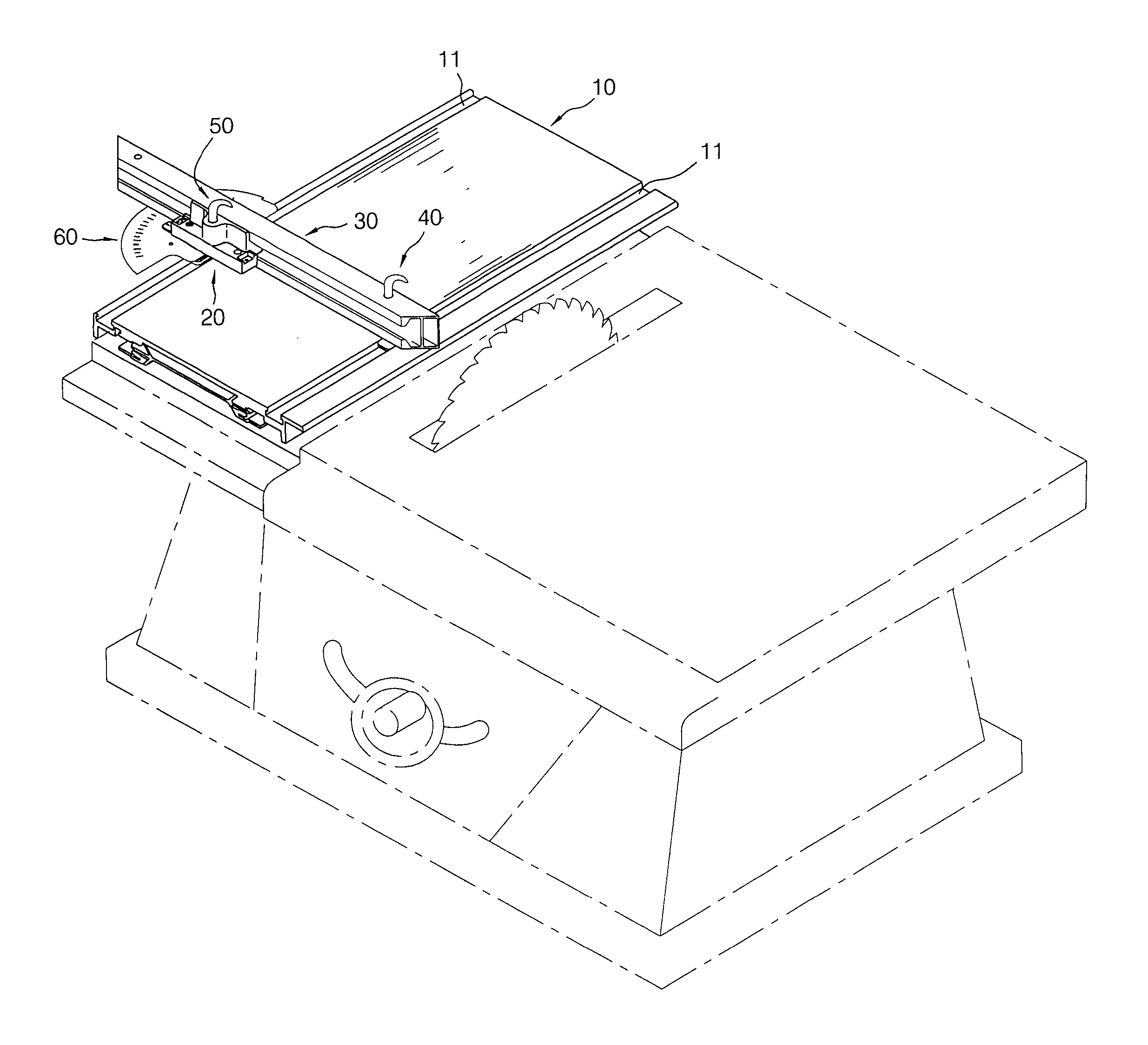
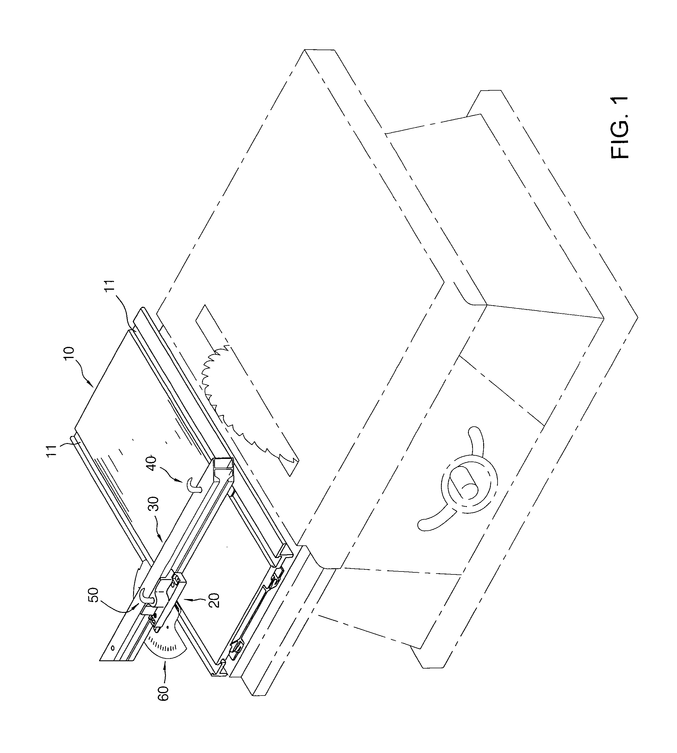
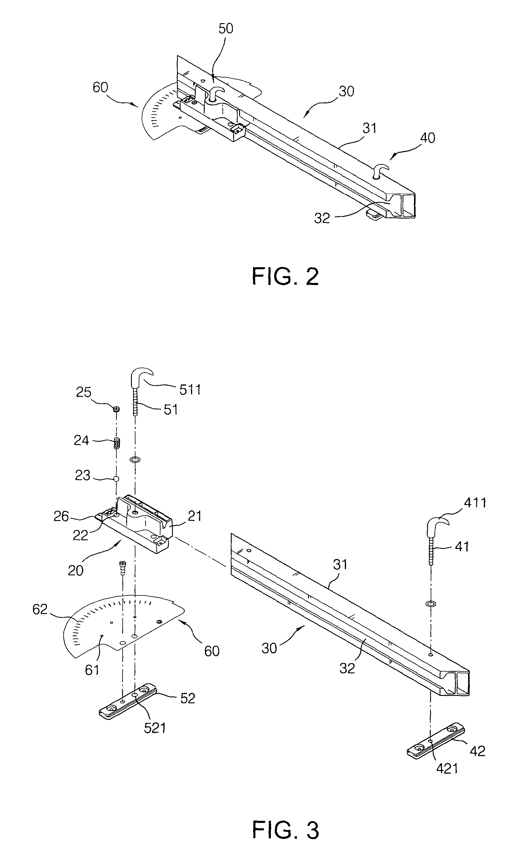
[0019] Referring to the drawings and initially to FIGS. 1-3, a feeding device for a table saw in accordance with the present invention comprises sliding board (10) adapted to be slidably mounted on one side of a worktable of the table saw and having a moving direction adapted to correspond to a saw blade of the table saw. A moving seat (20) is selectively slidably mounted on one side of the sliding board (10). A pushing rod (30) is laterally slidably mounted to the moving seat (20). A first locking device (40) and a second locking device (50) respectively extend through the pushing rod (30) and the moving seat (20) for confirming a cutting angle of a workpiece. A graduation plate (60) is securely mounted to a bottom of the moving seat (20).

[0020] The sliding board (10) includes two grooves (11) defined in two opposite sides thereof. The two grooves (11) are respective parallel to the moving direction of the sliding board (10).

[0021] The moving seat (20) includes a rail (21) latera...


PUM

PropertyMeasurementUnit
Angleaaaaaaaaaa

Abstract

A feeding device for a table saw includes a sliding board slidably mounted on one side of a worktable of the table saw and having a moving direction corresponding to a saw blade. The sliding board includes two grooves defined in two opposite sides thereof and respectively parallel to the moving direction of the sliding board. A moving seat is selective slidably mounted on one side of the sliding board. A pushing rod is laterally slidably mounted to the moving seat and has a first side forming a pushing face for abutting against a datum of a workpiece. A first locking device and a second locking device respectively extend through the pushing rod and the moving seat to selectively hold the pushing rod and the moving seat in place for confirming a cutting angle of the workpiece.

Description

BACKGROUND OF THE INVENTION [0001] 1. Field of the Invention [0002] The present invention relates to a feeding device, and more particularly to feeding device for a table saw. The feeding device of the present invention can be used to a long distance cutting. [0003] 2. Description of Related Art [0004] A conventional feeding device for a table saw comprises a moving seat slidably mounted on one side of a worktable of the table saw. A graduation plate is partially rotatably mounted to the moving seat and a pushing rod laterally extends from the graduation plate for abutting against a datum of a workpiece. A threaded rod upwards extends from the moving seat and penetrates through the graduation plate. A nut is screwed onto the threaded rod to hold the graduation plate in place after adjusting an operating angle. [0005] However, the adjusting range of the graduation plate on the conventional feeding device for a table saw is smaller than 180 degrees. Consequently, the conventional feed...

Claims


Application Information

Patent Timeline
IPC IPC(8): B23D47/02B27B25/10
CPCB27B25/10B23D47/025Y10T83/773Y10T83/8773Y10T83/6609
Inventor CHANG, CHIN-CHIN
Owner CHANG CHIN CHIN
Learn More