
Adjustable beam support

Inactive Publication Date: 2005-03-17
CARLSON BRUCE
View PDF24 Cites 26 Cited by
  • Summary
  • Abstract
  • Description
  • Claims
  • Application Information

AI Technical Summary

Problems solved by technology

The prior art teaches adjustable structural supports, leveling devices, decking supports, floor panels supports, and adjustable pier blocks, but does not teach a beam support channel mounted on an upper end of a supporting strut where the strut provides a threaded lower portion engaging a pier rotationally for raising and lowering the channel.

Method used


Image

  • Adjustable beam support
  • Adjustable beam support
  • Adjustable beam support

Examples


Embodiment Construction

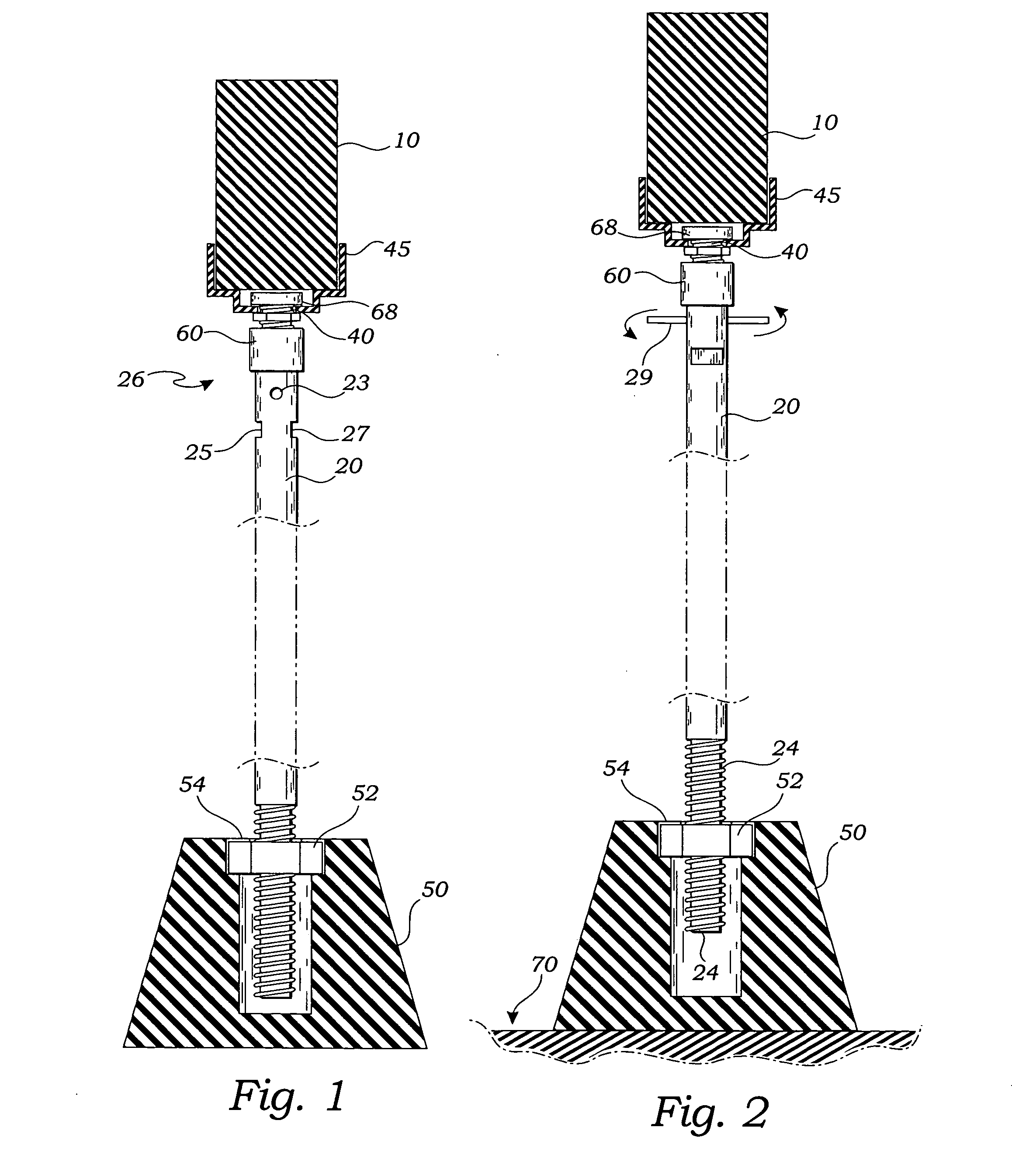
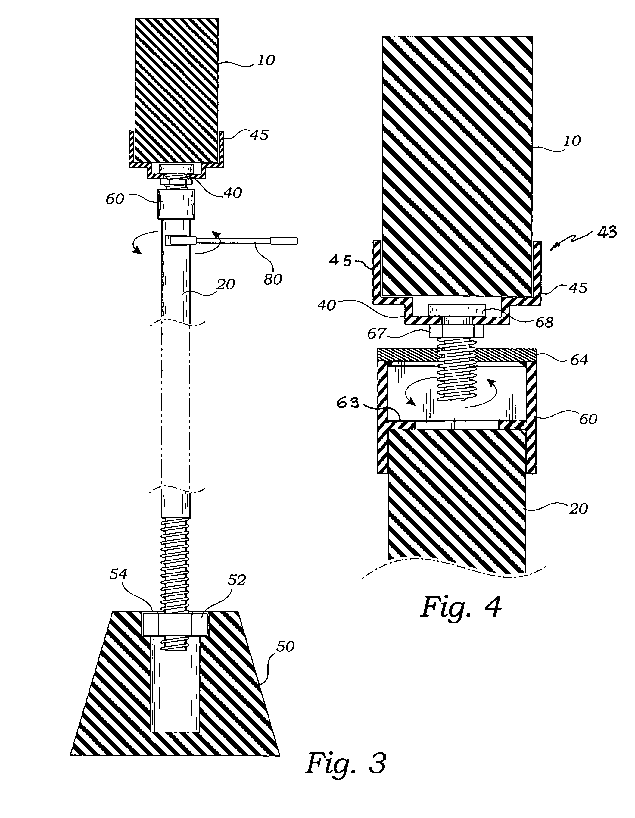
[0032] The above described drawing figures illustrate the invention in at least one of its preferred embodiments, which is further defined in detail in the following description.

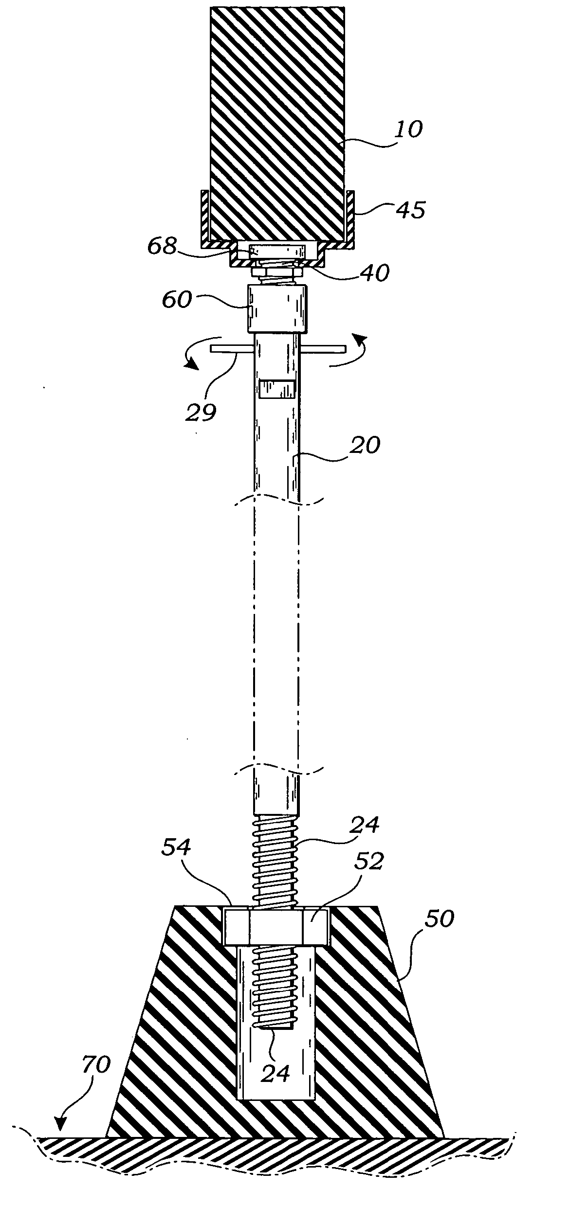
[0033] The present invention is an apparatus for supporting a structural beam 10 such as is used for supporting floors and ceilings in building construction, as shown in FIGS. 1-4. The apparatus provides a vertical strut 20, which may be made of wood or metal or ferro cement, for instance, and which provides at a lower end, an axially threaded portion 24 rotationally engaged with a pier 50 through pier nut 52. At an upper end 26 of strut 20, a strut cap 60 provides an axially threaded plate 64, as is best shown in FIG. 4 and has an internal annular flange 63. The annular flange 63 rests on the upper terminal end of strut 20 and the cap is of such size as to be able to rotate on strut 20. Strut cap 60 and plate 64 are fastened permanently together by welding or other well known means so that they form a sing...


PUM


Abstract

An vertical strut has, at a lower end, an axial threaded portion rotationally engaged with a pier, and at an upper end, a strut cap terminating with an axial threaded plate. A beam support channel is engaged with the threaded plate by a fastener. The support channel provides opposing L-shaped sidewalls spaced apart for engaging a beam, and a U-shaped well depending downwardly from the L-shaped sidewalls for receiving a head of the fastener.

Description

BACKGROUND OF THE INVENTION RELATED APPLICATIONS [0001] This application is a Continuation-In-Part Application of a prior filed, currently pending, application having serial number 10373452 and filing date of Feb. 24, 2003 and entitled: Adjustable Beam Support. FIELD OF THE INVENTION [0002] This invention relates generally to structural supports and more particularly to a vertically adjustable beam support with cost effective construction and simple operation. DESCRIPTION OF RELATED ART [0003] The following art defines the present state of this field: [0004] Anderson, U.S. 2002 / 0014573 describes a device and method for leveling a machine using a base with a central opening and a bolt detachably insertable through the opening of the base. The head of the bolt will mate with the opening in the base. A nut can then be screwed onto the bolt in order to lock it to the base. Two additional nuts will hold a machine anchor on the bolt. The nuts adjacent the anchor can be vertically adjusted...

Claims


Application Information

Patent Timeline
Patent Type & Authority Applications(United States)
IPC IPC(8): E04F15/02E04F15/024E04G11/48E04G25/06
CPCE04F15/02E04F15/02458E04G25/06E04G11/48E04F15/0247E04F2015/02061E04F15/02044E04G25/061
Inventor CARLSON, BRUCE
Owner CARLSON BRUCE
Learn More