Liquid cooled system module

a liquid cooled system and module technology, applied in the field of heat dissipation, can solve the problems of limited system architecture design, limited scaling and interchangeability of installed systems, and restricted migration paths between air cooled and liquid cooled systems

Inactive Publication Date: 2005-03-24
HEWLETT PACKARD DEV CO LP
View PDF14 Cites 51 Cited by
  • Summary
  • Abstract
  • Description
  • Claims
  • Application Information

AI Technical Summary

Problems solved by technology

Migration paths between air cooled and liquid cooled systems have been restricted.
This has limited system architecture design, which has in turn limited scaling

Method used


Image

  • Liquid cooled system module
  • Liquid cooled system module
  • Liquid cooled system module

Examples


Embodiment Construction

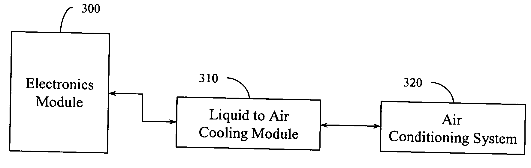
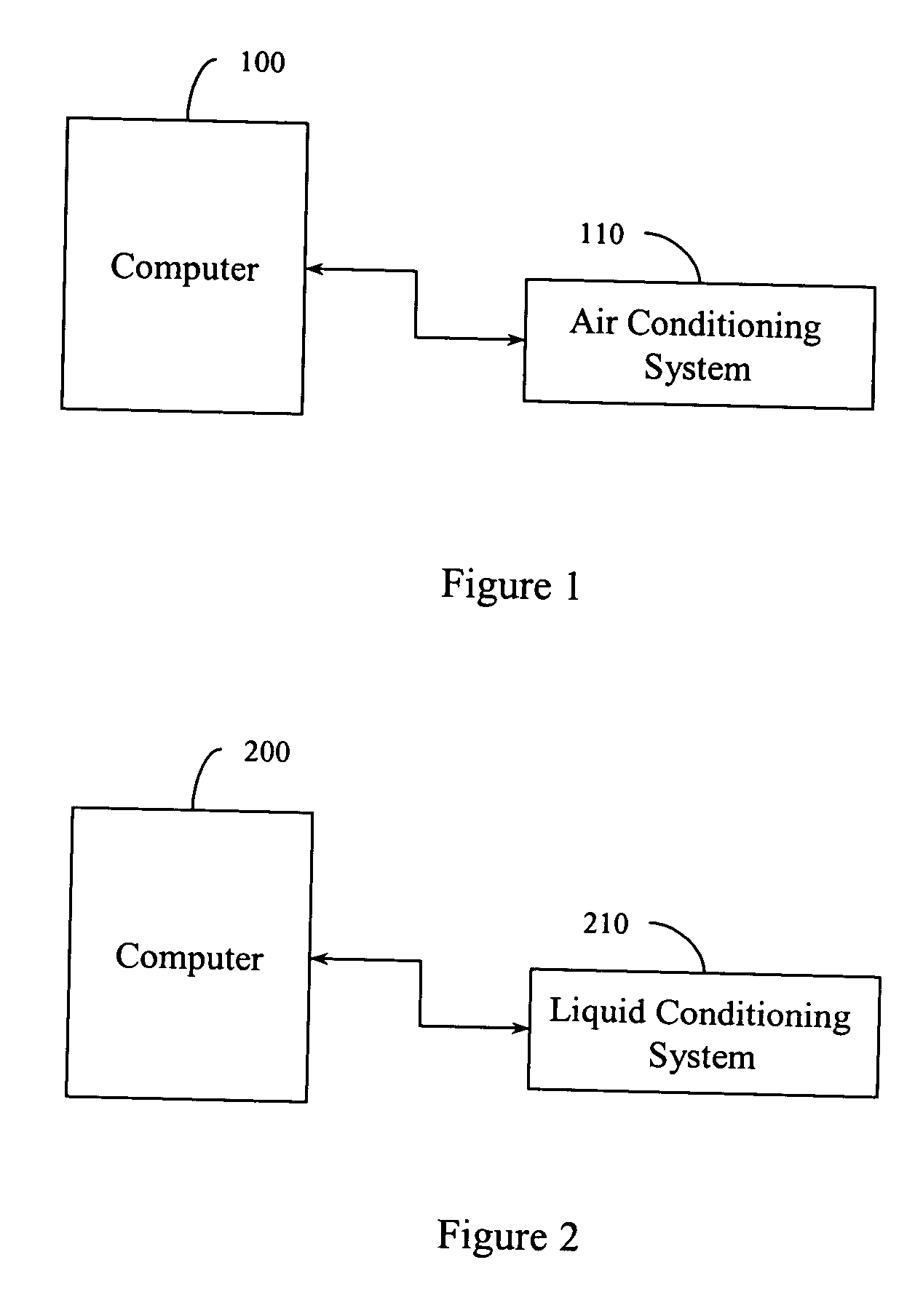
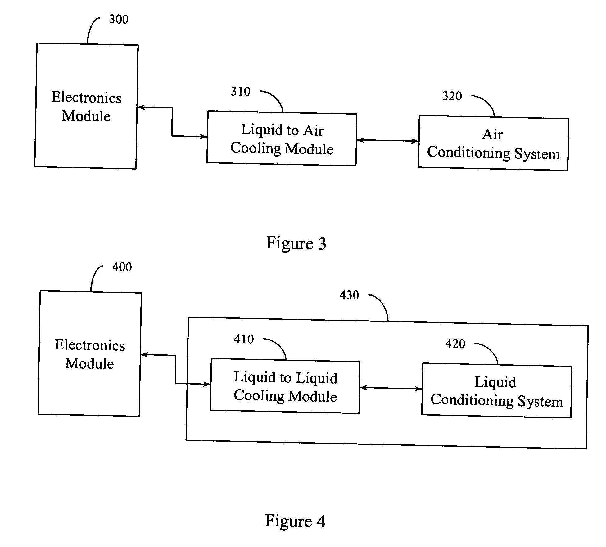
[0017] Electronics systems (e.g., computers) generate heat. Generally, electronics systems benefit from having this heat dissipated so that the electronics systems do not overheat. The heat may be dissipated by, for example, air, liquid, and so on. The example systems described herein facilitate designing electronic modules without considering whether the destination environment is air conditioned or liquid conditioned. Some electronics systems are located close together (e.g., mounted in racks). In a rack mounted configuration, an air path that had been available to dissipate heat from an electronic module may be blocked when another module is added to the rack. This can limit the size, type, number and so on of modules that can be mounted in a rack. Similarly, a rack located in a facility with a finite air conditioning capacity may not be able to house certain configurations due to the air conditioning limitations.

[0018] Some computer architectures can benefit from having electro...


PUM


Abstract

Example sealed electronics modules are described. The sealed electronics module may include electronics components. The sealed electronics module may also include one or more connectors configured to provide one or more detachable liquid connections to a liquid transporting apparatus. The liquid transporting apparatus may provide liquid communication between the sealed electronics module and an external liquid cooling module. The sealed electronics module may also include an apparatus for the cooling electronics components in the electronics module using liquid that is transported between the sealed electronics module and the external liquid cooling module.

Description

TECHNICAL FIELD [0001] The example systems and methods described herein relate generally to heat dissipation in electronics (e.g., computer) systems and to modules employed in liquid cooled system architectures. BACKGROUND [0002] Conventionally, electronics systems like computer systems have been air cooled. Some systems have been liquid cooled. Migration paths between air cooled and liquid cooled systems have been restricted. This has limited system architecture design, which has in turn limited scaling and interchangeability in installed systems. Additionally, electronics design has been intertwined with heat dissipation design, further limiting design options.BRIEF DESCRIPTION OF THE DRAWINGS [0003] The accompanying drawings, which are incorporated in and constitute a part of the specification, illustrate various example systems that illustrate various example embodiments of aspects of the invention. It will be appreciated that the illustrated element boundaries (e.g., boxes, gro...

Claims


Application Information

Patent Timeline
IPC IPC(8): H05K7/20
CPCG06F1/20H05K7/20763G06F2200/201
Inventor BELADY, CHRISTIAN L.
Owner HEWLETT PACKARD DEV CO LP
Why Eureka
Try Eureka