Method and system for 3-D object modeling

a technology of object modeling and modeling method, applied in the field of graphic modeling, can solve the problems of limited 3-d lenticular image present techniques, present techniques are not easily automated, present techniques may only provide an adequate depth simulation

Inactive Publication Date: 2005-03-24
FERY GUY ANDRE
View PDF4 Cites 5 Cited by
  • Summary
  • Abstract
  • Description
  • Claims
  • Application Information

AI Technical Summary

Problems solved by technology

However, the present techniques for providing 3-D lenticular images are limited in that they only provide for convenient simulation of depth between objects and the background, and between the objects themselves.
Moreover, t

Method used


Image

  • Method and system for 3-D object modeling
  • Method and system for 3-D object modeling
  • Method and system for 3-D object modeling

Examples


Embodiment Construction

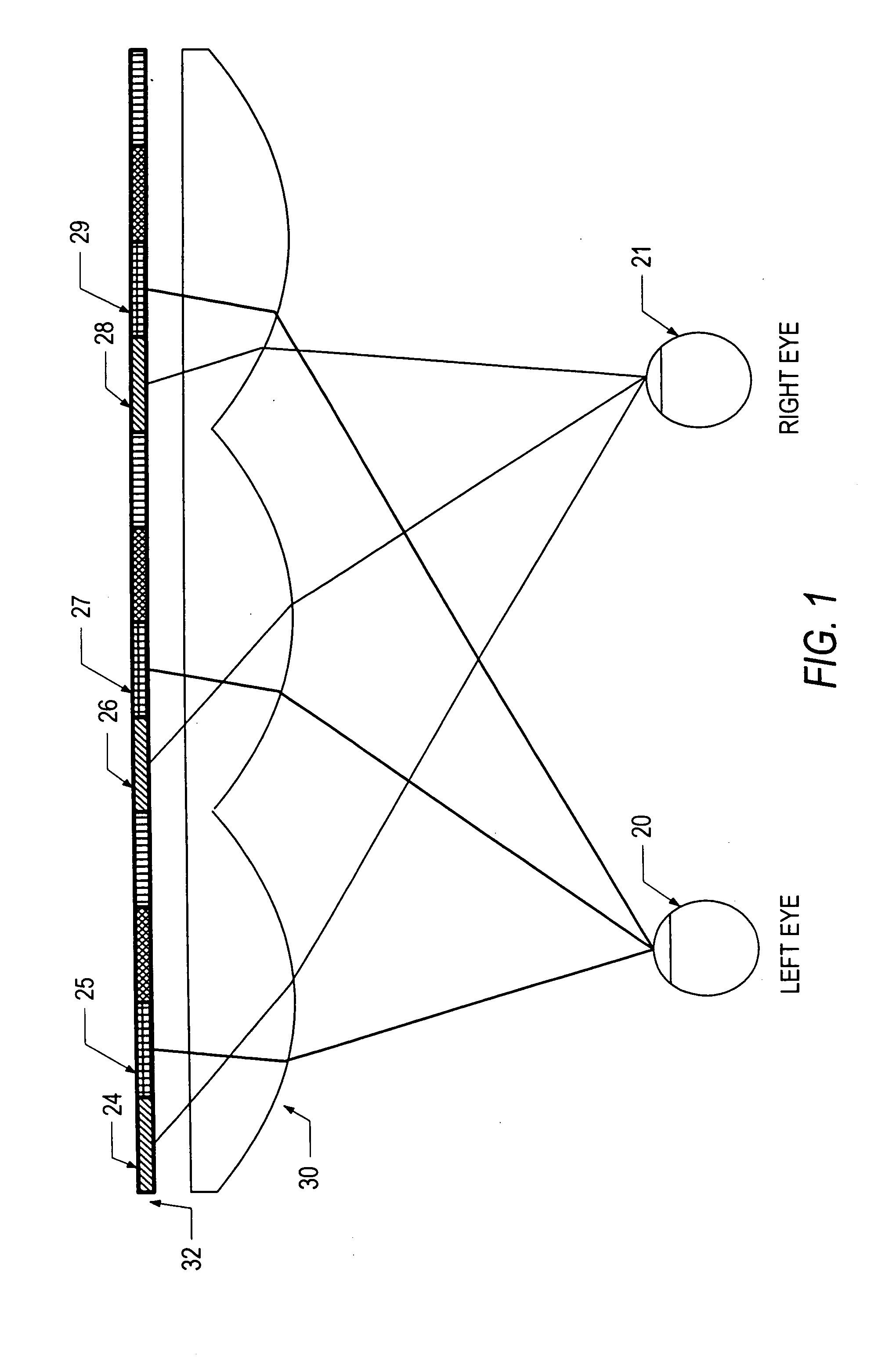
[0018]FIG. 1 illustrates a lenticular surface and a corresponding interlaced image 32. “Lenticule” is a synonym for “lens” but has come to mean a sheet of long thin lenses. The Lenticular surface preferably contains a series of cylindrical lenses 30 molded into a plastic substrate. Each lens focuses on a strip from an image on the back side of the lenticular surface 32. As illustrated in FIG. 1, the lenticular image is positioned so that the line of sight for each one of an observer's eyes 20, 21 is focused onto different groups of strips 24, 26, 28 and 25, 27, 29, associated with different images. The lenticular sheet is preferably made so that the back side of the sheet 32 is exactly one focal length behind the lens 30 so that the image data emerges collimated from each individual lens.

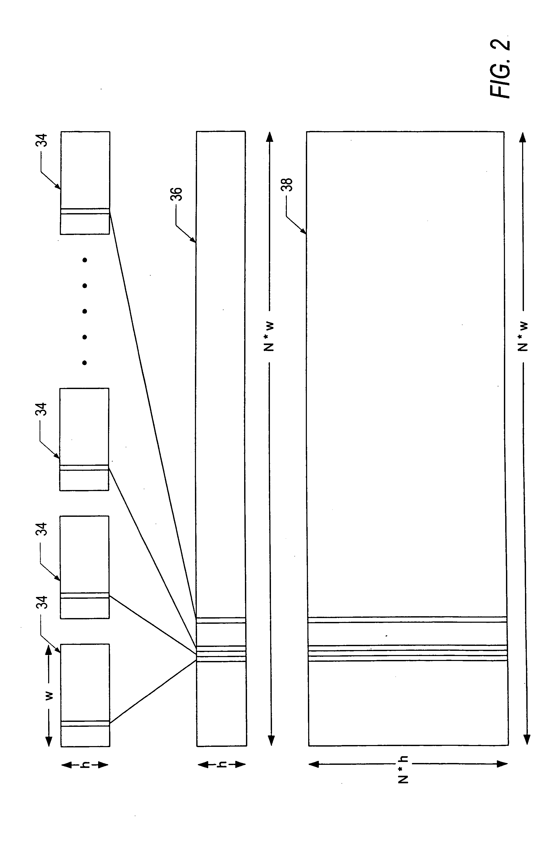
[0019]FIG. 2 illustrates a common arrangement of frame portions in an interlaced image. The illustrated case is for N sub-images 34 that are interlaced to form a composite 36 that is N times wider ...


PUM


Abstract

3-D views of a 2-D image containing objects are provided by simulation of inter-object volume and intra-object volume. Intra-object volume is simulated by defining a plurality of volumetric slices from the object and assigning relative volume values to each. Multiple views of the object are simulated by displacing each slice in accordance with the defined volumetric effect as part of an animation sequence simulating progressive movement about a focus point of the object.

Description

CROSS-REFERENCE TO RELATED APPLICATION [0001] This application is a continuation of and claims priority from U.S. patent application Ser. No. 10 / 211,500, entitled “Method and System for 3-D Object Modeling” filed Aug. 2, 2002, now pending, which is incorporated herein by reference.FIELD OF THE INVENTION [0002] The present invention relates to graphical modeling, specifically the invention relates to volumetric simulation from a two dimensional input image. BACKGROUND OF THE INVENTION [0003] Stereoscopic systems present a viewer with an image of an object such that the object appears to have depth. The wide variety of techniques to provide such images commonly involve presenting different views of the object to each eye to simulate such images. Traditional stereoscopic systems employ an apparatus that keeps the left and right eye images directed solely at the appropriate eye such as by employing helmets or shutter glasses. [0004] Autostereoscopic displays do not require special viewi...

Claims


Application Information

Patent Timeline
IPC IPC(8): G06DG06T13/00G06T15/70G06T17/10H04N7/01
CPCG06T17/10
Inventor FERY, GUY ANDRE
Owner FERY GUY ANDRE
Why Eureka
Try Eureka