Image recording apparatus

Inactive Publication Date: 2005-03-24
FUJIFILM CORP
View PDF4 Cites 21 Cited by
  • Summary
  • Abstract
  • Description
  • Claims
  • Application Information

AI Technical Summary

Benefits of technology

[0011] The present invention has been contrived in view of such circumstances, and an object thereof is to provide an image recording apparatus that can reliably retouch recording defects without wasting the recording medium even if missing print or other recording defects are generated on the recording medium due to nozzle clogging or other image-recording element defects.
[0013] In accordance with the present invention, defective streaks and spots can be accurately restored because a configuration is adopted in which defective pixels are detected after image recording, only the recording medium on which defective pixels are detected is conveyed to the re-recording position, the defective pixel positions are redetected when recording is performed for a second time, and the defective pixels are restored.
[0014] Preferably, pixels surrounding the defective pixels are printed to interpolation when the re-recording is performed on the recording medium with the recording head. More preferably, the pixels surrounding the defective pixels are printed to interpolation with a density that is less than the density during the previous recording. The restored portion can thereby be made more visible.
[0015] Preferably, the image recording apparatus further comprises: a relative position varying device which varies relative positions of the recording medium and the recording head in array direction of the image-recording elements when the re-recording is performed on the recording medium with the recording head. Defective pixels can thereby be rapidly restored without carrying out actions to repair the defective image-recording elements.
[0017] In accordance with the image recording apparatus related to the present invention as described above, recording defects can be reliably restored without wasting the recording medium even if missing print or other recording defects are generated on the recording medium due to a malfunction of image-recording elements.

Problems solved by technology

In such an inkjet printer, due to clog of nozzles in the print head or a soiled meniscus surface on the ink in the head or other factors, ink may not be discharged or may not be discharged to a proper flight direction, hence missing spots may occur during printing for this reason.
Such missing print is inconspicuous due to the considerable overlap in the shuttle-scan method, but nonuniformity by print defects occurs frequently in the case of a line head.
Nevertheless, as cited in Japanese Patent Application Publication No. 9-24627, the direction of the once printed recorded paper is reversed, print defects are detected, and a determination is made as to whether to reprint, so regardless of the presence of a print defect, and the recording paper always reciprocates through the print head, therethrough productivity is low.
Furthermore, only a normally functioning dot print element disposed at a prescribed distance from the defective dot print elements is used for printing, bringing about a drawback whereby the print defects are not necessarily completely retouched due to the skewing or other effect of the recording paper.
In the invention cited in Japanese Patent Application Publication No. 11-334047, there are drawbacks in that the apparatus configuration has considerable redundancy, because a compensating auxiliary head must be jointly provided for each color in addition to a regular line head.
In the invention cited in Japanese Patent Application Publication No. 2003-145734, when a defective nozzle is detected, an attempt is made to shift the recording position of the barcode, or rotate the barcode by 90° to avoid streaking or other print defects in advance in the next barcode, and there is no provision for reprinting or taking other remedial action to retouch the recording medium with a print defect, therethrough there is a drawback in that the recording medium printed defectively is wasted

Method used


Image

  • Image recording apparatus
  • Image recording apparatus
  • Image recording apparatus

Examples


first embodiment

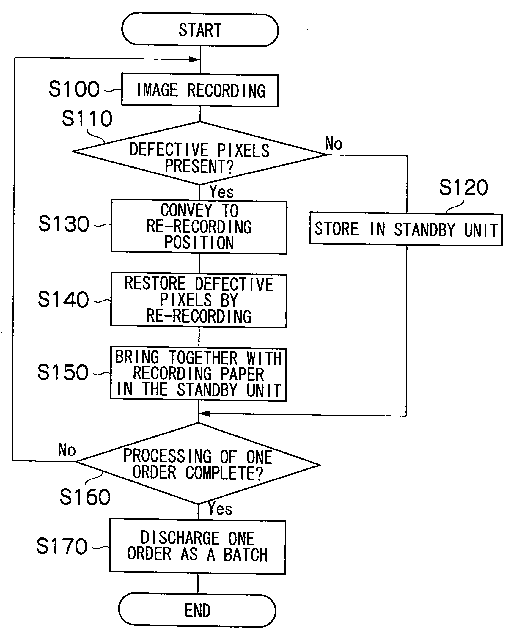
[0068] The effect of the first embodiment is described below in accordance with the steps shown in the flowchart FIG. 4.

[0069]FIG. 4 is a flowchart showing the processing flow for restoring defective pixels as an effect of the image recording apparatus 10 of the present embodiment. The flowchart in FIG. 4 shows the processing of a single order, and in the actual work process it is commonplace to process a plurality of orders, so even if processing for a single order is completed, overall processing may not be complete and the processing shown the FIG. 2 may be repeatedly executed.

[0070] The first embodiment is one in which the first recording cycle is conducted on cut paper (sheets), and defective pixels are detected each time an image (frame) is recorded in the order. When there are no defects, the recorded paper is stored in the standby unit, and when defects have been detected, the recorded paper is returned to the recording unit 12, defective pixels are restored by recording th...

second embodiment

[0093] Next, the present invention is described.

[0094]FIG. 6 is a schematic block diagram showing a second embodiment of the image recording apparatus of the present invention. The image recording apparatus of the second embodiment shown in FIG. 6 performs the first image recording directly to the roll paper (continuous paper), detects defective pixels for each image frame after the images have been recorded, forms a loop portion of uncut paper in standby until the processing of a single order is completed, returns the recording paper of a single order before the next order is processed when defective pixels have been detected, forms a loop portion in front of the recording unit, records solely the images with defective pixels, and cuts the paper with the images (frames) of a single order as a batch.

[0095] In other words, as shown in FIG. 6, the image-recording apparatus 100 has a printing unit 112 with a plurality of print heads 112K, 112C, 112M, and 112Y provided for each ink col...


PUM


Abstract

The image recording apparatus which records an image to a recording medium with a full-line recording head in which a plurality of image-recording elements are arrayed across a length that corresponds to an entire width of the recording medium while at least one of the recording medium and the recording head is conveyed in a direction that is substantially orthogonal to a width direction of the recording medium, and the recording head and the recording medium are relatively moved, the image recording apparatus comprises: a defective pixel detecting device which detects defective pixels in the image recorded on the recording medium by the recording head; a recording medium conveying device which conveys the recording medium on which the defective pixels have been detected, to a position for re-recording the image with the recording head when the defective pixels have been detected in the image recorded on the recording medium; and a defective pixel position detecting device which detects positions of the defective pixels before re-recording the image with the recording head on the recording medium on which the defective pixels have been detected, wherein, when the defective pixels are detected, the defective pixels on the recording medium are restored by moving at least one of the recording head and the recording medium, and re-recording the pixels in the detected defective pixel positions by using different image-recording elements than the image-recording elements that have recorded the defective pixels, or by repairing defects of the image recoding elements which have recorded the defective pixels, and re-recording the image.

Description

BACKGROUND OF THE INVENTION [0001] 1. Field of the Invention [0002] The present invention relates to an image recording apparatus, and more particularly, to a technique for restoring recording defects by the image-recording elements of an inkjet recording apparatus or another image recording apparatus for recording images on a recording medium with a recording head having a plurality of image-recording elements. [0003] 2. Description of the Related Art [0004] An inkjet image recording apparatus has an inkjet head (print head) in which a plurality of nozzles are arrayed, and the apparatus forms an image on a recording medium by moving the print head and recording medium in relation to each other, while ink is discharged from the nozzles. [0005] In such an inkjet printer, due to clog of nozzles in the print head or a soiled meniscus surface on the ink in the head or other factors, ink may not be discharged or may not be discharged to a proper flight direction, hence missing spots may ...

Claims


Application Information

Patent Timeline
IPC IPC(8): B41J2/165
CPCB41J2/2146B41J2/16579
Inventor KOJIMA, TOSHIYA
Owner FUJIFILM CORP
Why Eureka
Try Eureka