Mounting bracket for an electrical box

a technology for mounting brackets and electrical boxes, which is applied in the direction of curtain suspension devices, filing appliances, coupling device connections, etc., can solve the problems of inability to guarantee, inconvenient installation, and inability to mount studs,

Inactive Publication Date: 2005-03-31
THOMAS & BETTS INT INC
View PDF65 Cites 73 Cited by
  • Summary
  • Abstract
  • Description
  • Claims
  • Application Information

AI Technical Summary

Problems solved by technology

Also, there is no guarantee that all the boxes will be positioned at the same depth within the wall cavity which is important so that any dry-wall ring or other device subsequently secured to the box will fit properly on the wall material.
However, if the architectural plans call for the box or boxes to be mounted some distance from a stud, then these stud-mounting means are futile.
While both are somewhat easy to mount, the horizontal wall-mounted brackets suffer from the need to insure that the bracket is properly positioned on the stud if the distance of the box above the floor is critical (such as to comply with local building codes and regulations).
Likewise, the floor-mounted bracket suffers from a deficiency if its upper cantilevered region is unsupported such that it can sway or pivot into or away from the wall cavity.
However, this feature will, obviously, interfere with any insulation or vapor barrier in the wall cavity or with any other service item located in the wall at that location.
While each of the above patents may be suitable for their intended purpose, they are also lacking to some degree.
Those brackets that incorporate a far side support interfere with the placement of insulation or vapor barrier in the wall cavity due to the support itself which extends to the back wall.
Additionally, these far side supports may also interfere with any other service item located in the wall at that location or they may block the installer's access to the electrical box itself.
These far side supports are also lacking in that they require one or more tabs to be bent thus meaning that the material must be thin enough to allow bending yet if bent too much, can break thus rendering this feature useless.

Method used


Image

  • Mounting bracket for an electrical box
  • Mounting bracket for an electrical box
  • Mounting bracket for an electrical box

Examples


Embodiment Construction

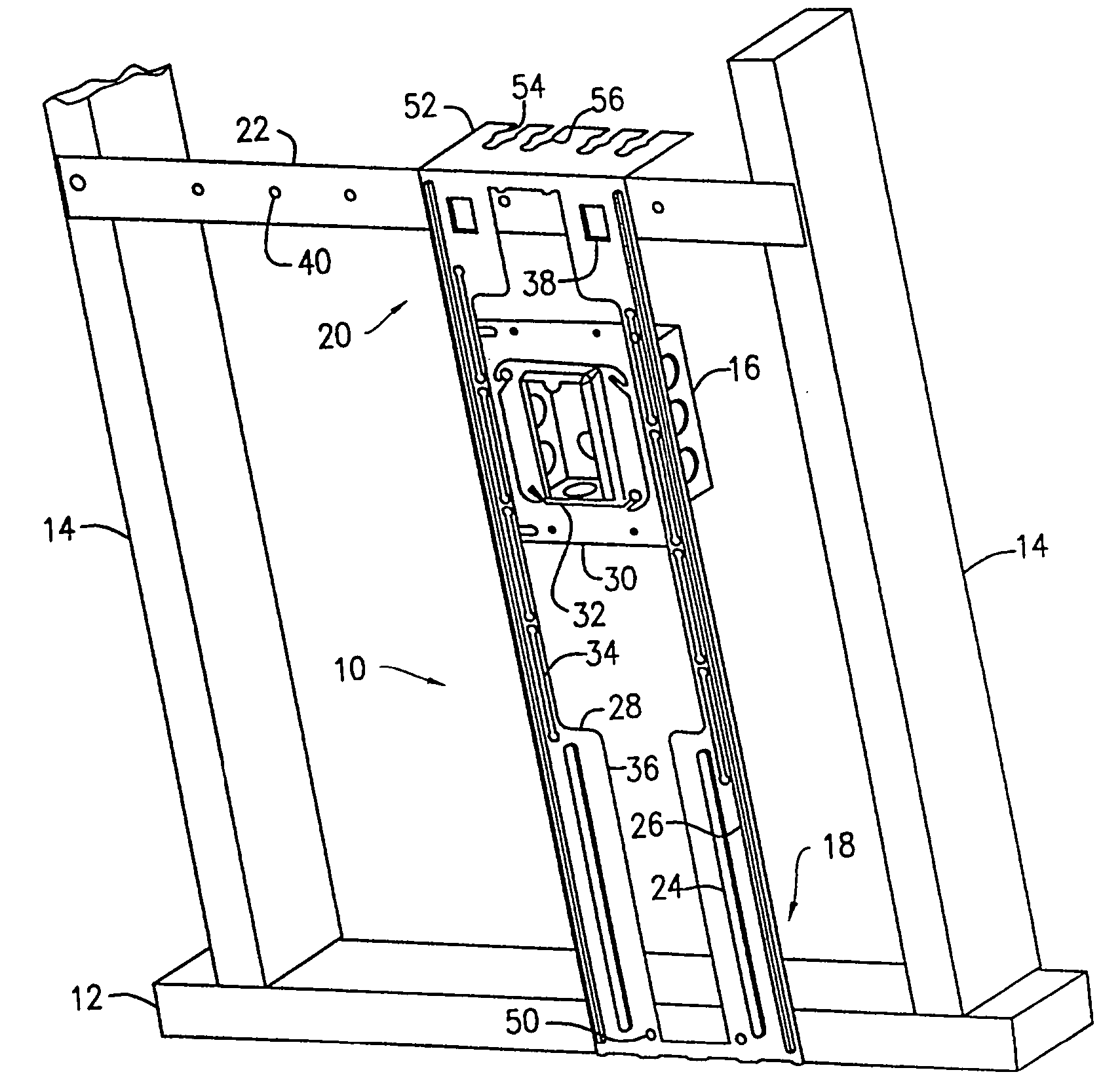
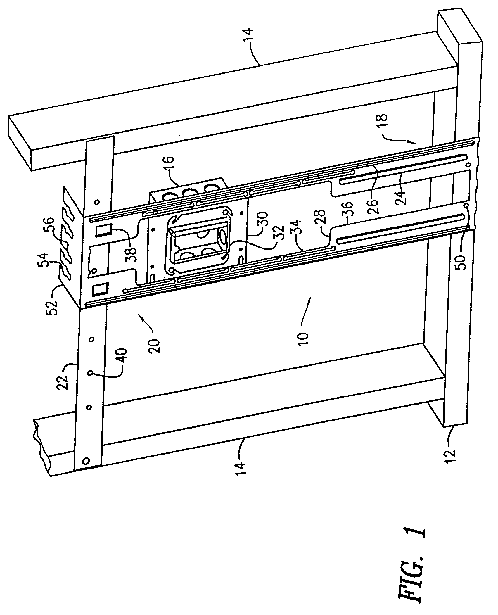
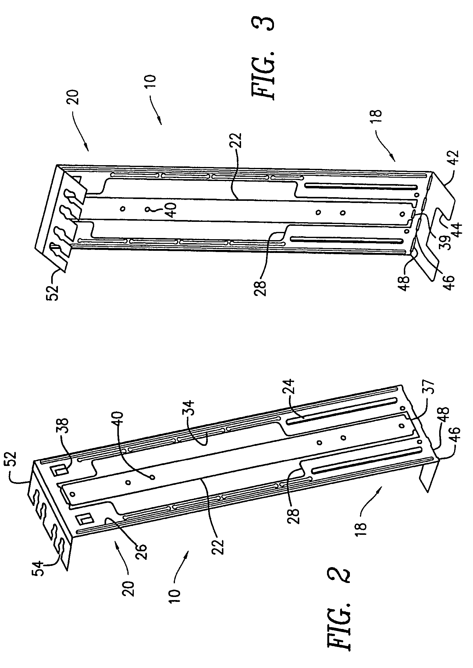
[0029] Referring initially to FIGS. 1-3, there is shown in this embodiment bracket 10 extending vertically from floor track 12 between two adjacent wall studs 14 of a building. Bracket 10 is elongated in shape and is shown as being constructed from thin metal material, but other materials are equally suitable and bracket 10 need not be unitary as illustrated. Bracket 10 is designed to mount an electrical box 16 a desired distance above the floor of the building within a wall cavity between adjacent studs 14, this box 16 abutting the back surface of bracket 10.

[0030] A lower portion 18 of bracket 10 can be directly mounted to floor track 12 such as via screws or nails. This lower portion can also be slightly offset for both better securement to the floor track and to inset the remainder of bracket 10 slightly into the wall structure in order to accommodate the thickness of any plaster ring or other plate that may be mounted to the front side of bracket 10.

[0031] Upper portion 20 of...


PUM


Abstract

An apparatus for mounting an electrical box within a wall cavity of a building, this wall cavity being defined by a plurality of wall supports. The apparatus consists of an elongated bracket having first and second mounting regions thereof and also configured to support an electrical box therefrom. At least the first mounting region is configured to be supported from a first wall support. An elongated bar is removably secured to the bracket with this bar being configured to secure the second mounting region of the bracket to a second wall support. This bar may be fully contained within the confines of the bracket or it may be removably secured alongside one edge region of the bracket. Preferably, the bar is stamped from the same metal plate that comprises the bracket.

Description

[0001] Incorporated by reference is U.S. Provisional Application No. 60 / 507,024 filed Sep. 29, 2003 and U.S. Provisional Application No. 60 / 561,641 filed Apr. 13, 2004. Reference to these earlier applications may be desired for further background, explanation and / or description.FIELD OF THE INVENTION [0002] This invention pertains to a bracket for mounting electrical boxes within the walls of a building and more particularly to a mounting bracket incorporating a break-away support used to secure one end of the mounting bracket to a wall support. BACKGROUND OF THE INVENTION [0003] There are many different methods used to secure electrical boxes within the walls of a building. The most common is, of course, to secure the box directly to the stud. The advantage of this system is that installation is quick and simple but there is no guarantee that all the boxes secured in this fashion will be the same height off the floor. Also, there is no guarantee that all the boxes will be positione...

Claims


Application Information

Patent Timeline
Patent Type & Authority Applications(United States)
IPC IPC(8): H02G3/12
CPCY10S248/906H02G3/125
Inventor DINH, CONG
Owner THOMAS & BETTS INT INC
Why Eureka
Try Eureka