
Power connector having latch devices on opposite sides and an Anti-mismating structure

a technology of latching device and power connector, which is applied in the direction of electrical equipment, connection, coupling device connection, etc., can solve the problems of limited space above the above mentioned connector assembly cannot be used, and the latch cannot be located on the top surface of the housing. , to achieve the effect of improving the latching

Inactive Publication Date: 2005-04-07
HON HAI PRECISION IND CO LTD
View PDF11 Cites 3 Cited by
  • Summary
  • Abstract
  • Description
  • Claims
  • Application Information

AI Technical Summary

Benefits of technology

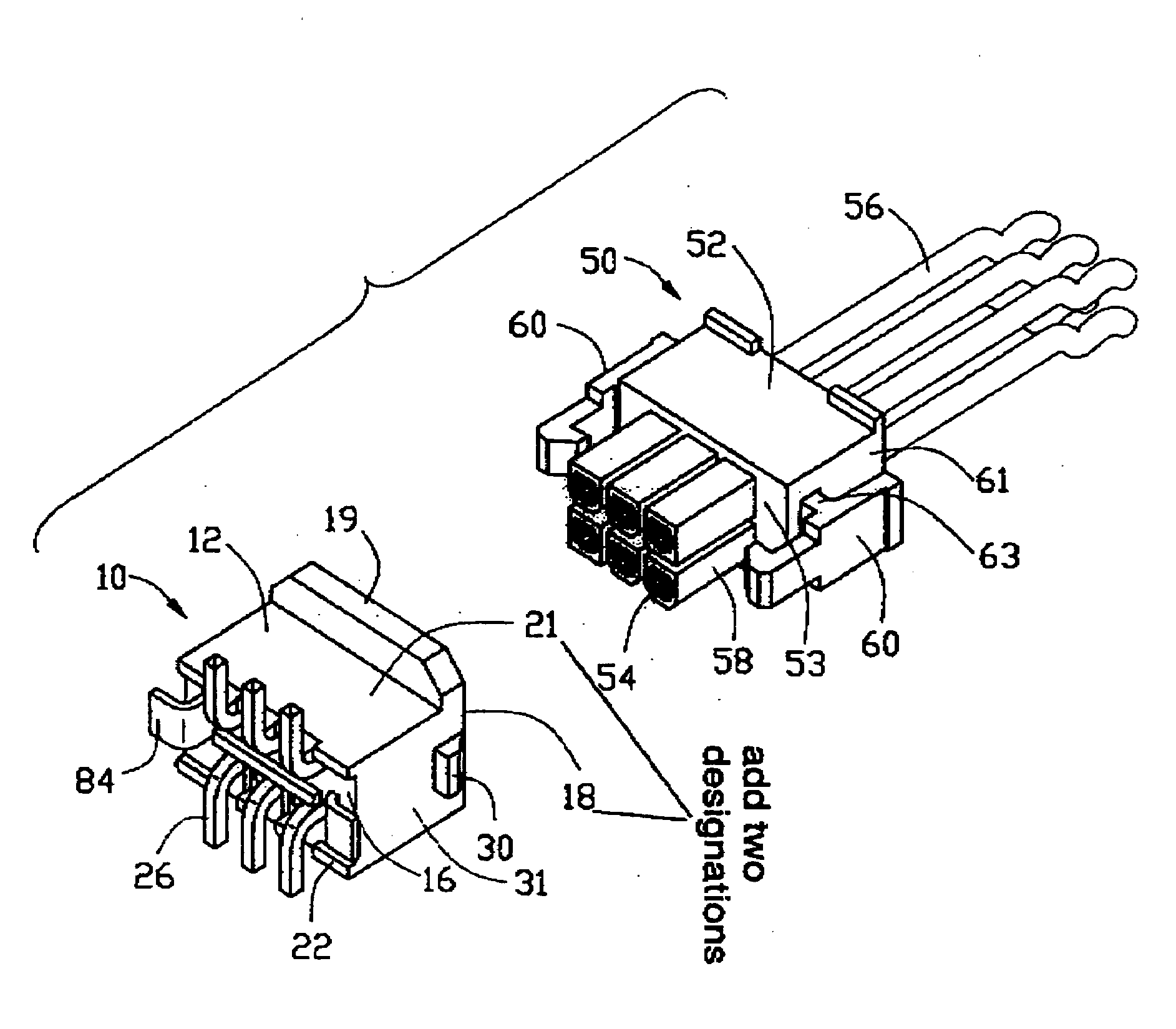
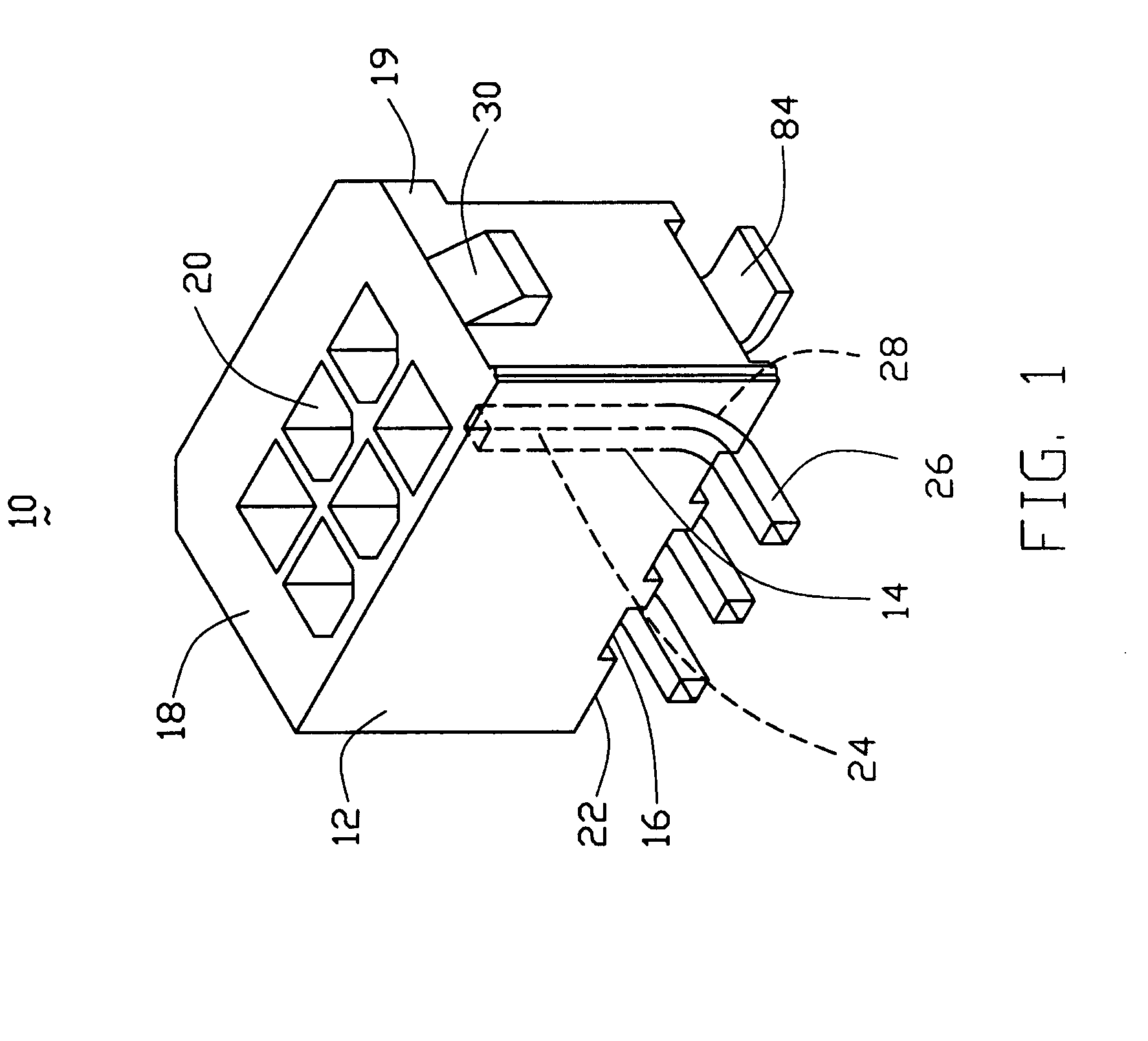
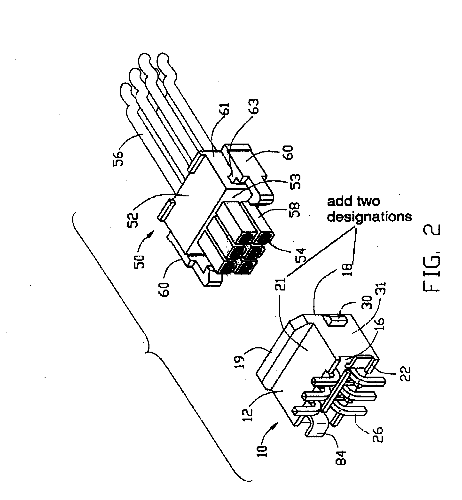
The present invention provides a power connector with improved latching means for securely engaging with a mating connector. The connector assembly includes a header connector and a cable end connector engageable with the header connector. The header connector has a housing with a number of passageways and conductive contacts each with a mating portion received in corresponding passageways and a tail portion extending below the bottom surface of the housing. The tail portions extend in a single plane parallel with the bottom surface of the housing such that they are surface mountable onto corresponding solder pads on the substrate. The housing also has a pair of wedgy blocks on opposite side surfaces thereof. The cable end connector has a housing with a pair of latches on opposite side surfaces thereof. The latches engage with the wedgy blocks when the cable end connector completely mates with the header connector to avoiding disengagement of the connectors.

Problems solved by technology

However, in some instance, due to the restriction of the space, the latch cannot be located on the top surface of the housing.
Thus, the above mentioned connector assembly cannot be used in the instance where the space above the top surface of the housing is limited.

Method used


Image

  • Power connector having latch devices on opposite sides and an Anti-mismating structure
  • Power connector having latch devices on opposite sides and an Anti-mismating structure
  • Power connector having latch devices on opposite sides and an Anti-mismating structure

Examples


first embodiment

[0015]FIGS. 1-3 illustrate a connector system including a header connector 10 and a cable end connector 50. The header connector 10 includes a housing of insulative material 12 and a number of contact of conductive material 14 assembled to the housing 12. The housing 12 has a bottom surface 16 facing a substrate 80 (sometimes called printed board) after the header connector 10 is mounted onto the substrate 80 and an opposite top surface 18 and defines a plurality of passageways 20 between the bottom and top surfaces 16, 18. These passageways 20 are arranged in rows, for example two rows and each row has three passageways 20. The passageways 20 impress at least two different geometries on the top surface 18 of the housing 12 such that there is a pole that may be inserted into the passages having one of the geometry but may not be inserted into the passages having the other geometry. Several stand-offs 22 are provided on the bottom surface 16 of the housing 12. Each contact 14 include...

second embodiment

[0017]FIGS. 4-6 illustrate the connector system including a right-angle header connector 110 and the cable end connector 50 disclosed above. The header connector 110 is similar to the header connector 10 but the header connector 10“stands” on the substrate 80 and engages with the cable end connector in a direction perpendicular to the substrate 80 while the header connector 110“lies” on the substrate 80 and engages with the cable end connector in a direction parallel with the substrate 80. The header connector 110 includes a housing 112 of insulative material, a plurality of contacts 114 of conductive material attached to the housing 112. The housing 112 has a bottom surface 115 facing the substrate 80 when the header connector 110 is mounted onto the substrate, a front surface 116 engageable with the cable end connector 50, a rear surface 118 distanced from the front surface 116 and defines a plurality of passageways 120 between the front and rear surfaces 116, 118. The housing pro...


PUM


Abstract

A connector assembly includes a header connector (10, 110) and a cable end connector (50) engageable with the header connector. The header connector includes an insulative housing (12, 112) defining a number of passageways (20, 120) and a number of conductive contacts (14, 114) each having a mating portion (24, 124) received in corresponding passageways and a tail portion (26, 126) extending below a bottom surface (16, 116) of the housing. The tail portions extend in a single plane parallel with the bottom surface of the housing such that they are surface mountable onto corresponding solder pads on the substrate. The housing provides a pair of wedgy blocks (30, 130) on opposite side surface (31, 131) thereof. The cable end connector includes a housing (52) providing a pair of latches (60) on opposite side surfaces (61) thereof. The latches engage with the wedgy blocks when the cable end connector completely mates with the header connector to avoiding disengagement of the connectors.

Description

BACKGROUND OF THE INVENTION [0001] 1. Field of the Invention [0002] The present invention relates to a power connector having latching means on opposite sides thereof for securely engaging with a mating connector mounted on a substrate. [0003] 2. Description of the Related Art [0004] U.S. Pat. No. 5,342,221 discloses a connector assembly including a board mounting connector and a cable end connector matable with each other. The board mounting connector may lie on a substrate and defines a plurality of passageways such that the board mounting connector is matable with the cable end connector in a direction parallel with the substrate. The cable end connector includes an insulative housing and a number of conductive contacts attached to the housing. The housing includes a front surface adapted for mating with the cable end connector and a rear surface distanced from the front surface. The housing provides a number of poles protruding forward from the front surface thereof and a plural...

Claims


Application Information

Patent Timeline
Patent Type & Authority Applications(United States)
IPC IPC(8): H01R13/627
CPCH01R13/6273H01R12/57
Inventor SPINK, WILLIAM E. JR.
Owner HON HAI PRECISION IND CO LTD
Learn More