Recording method and reproduction method suitable for recording/reproduction of AV data, and recording drive and reproduction drive, information recording system and information reproduction system, and information recording medium for such methods

a recording method and av data technology, applied in the field of recording/reproducing information on an information recording medium, can solve the problems of significant delay in the recording or reproduction process, inability to properly record, and inability to smooth and smooth the effect of recording, and achieve the effect of minimizing any delay caused by a defective region

Inactive Publication Date: 2005-04-14
PANASONIC CORP
View PDF5 Cites 8 Cited by
  • Summary
  • Abstract
  • Description
  • Claims
  • Application Information

AI Technical Summary

Benefits of technology

[0079] Thus, the invention described herein makes possible the advantages of (1) providing a data structure for a disk medium which permits real-time recording / reproduction of AV data by forestalling seek operations to a physically distant spare area so as to minimize any delay caused by a defective region; and (2) providing a data recording / reproduction method for use with such a data structure.

Problems solved by technology

If the sector address which has been read includes an error, the recording cannot occur properly because of inability to identify the right location.
Thus, a significant delay occurs during a recording or reproduction process if any defective regions (e.g., 2623 or 2625) exist in the user area 2621.
However, such delay may well be critically problematic in real-time recording and / or smooth reproduction of data containing digital video and audio data (hereinafter referred to as “AV data”).
For example, problems such as partial loss of AV data, noise generation, inability to perform smooth reproduction, may occur.

Method used


Image

  • Recording method and reproduction method suitable for recording/reproduction of AV data, and recording drive and reproduction drive, information recording system and information reproduction system, and information recording medium for such methods
  • Recording method and reproduction method suitable for recording/reproduction of AV data, and recording drive and reproduction drive, information recording system and information reproduction system, and information recording medium for such methods
  • Recording method and reproduction method suitable for recording/reproduction of AV data, and recording drive and reproduction drive, information recording system and information reproduction system, and information recording medium for such methods

Examples


example 1

[0112] Hereinafter, the present invention will be described by way of example, with reference to the accompanying figures.

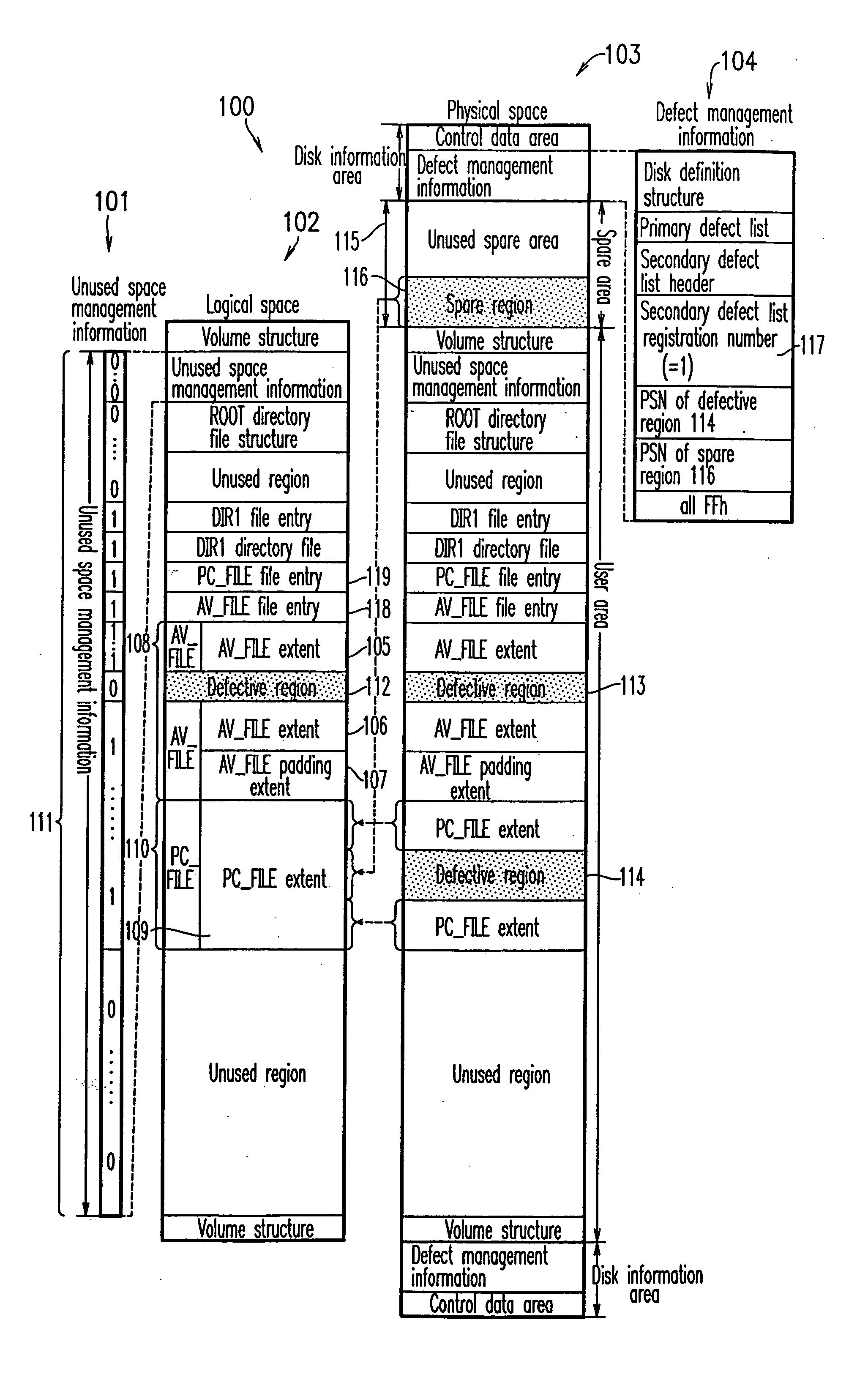
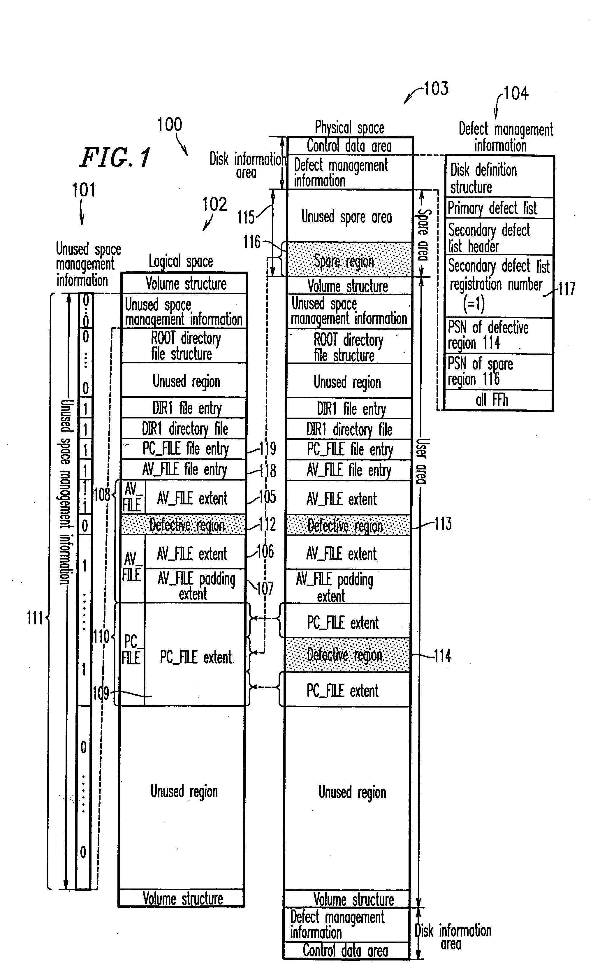
[0113]FIG. 1 shows a data structure 100 of a disk medium according to Example 1 of the present invention. In the data structure 100 shown in FIG. 1, a ROOT directory includes a DIR1 directory, where the DIR1 directory includes two files, namely, an “AV_FILE” file 108 for storing AV data and a “PC_FILE” file 110 for storing computer data. The description of the elements which have already been described with reference to FIG. 26 in connection with the conventional technique is omitted. Only the elements which form the features of the invention will be described.

[0114] In a logical space 102 shown in FIG. 1, the “AV_FILE” file 108 includes three extents, namely, an AV_FILE extent 105, an AV_FILE extent 106, and an AV_FILE padding extent 107. The PC_FILE 110 includes a PC_FILE extent 109. The example shown in FIG. 1 illustrates a case where a defective region 112 ...

example 2

[0191] Next, with reference to the figures, an information recording / reproduction system 1500 according to Example 2 of the present invention for recording or reproducing data on the disk medium shown in FIG. 1 will be described, with respect to its structure and operations.

[0192]FIG. 15 is a block diagram illustrating the structure of the information recording / reproduction system 1500 according to Example 2 of the present invention. Hereinafter, the respective elements of the information recording / reproduction system 1500 will be described. The descriptions of those elements which have their counterparts in the information recording / reproduction system 400 shown in FIG. 4 will be omitted.

[0193] As shown in FIG. 15, the information recording / reproduction system 1500 includes an upper control apparatus 1510, a disk recording / reproduction drive 1520, a magnetic disk apparatus 450, an AV data output section 460, an AV data input section 470, and an IO / bus 480.

[0194] The upper contro...

example 3

[0232] Next, with reference to the figures, an information recording / reproduction system 3000 according to Example 3 of the present invention for recording or reproducing data on the disk medium shown in FIG. 1 will be described, with respect to its structure and operations.

[0233]FIG. 20 is a block diagram illustrating the structure of the information recording / reproduction system 3000 according to Example 3 of the present invention. Hereinafter, the respective elements of the information recording / reproduction system 3000 will be described. The descriptions of those elements which have their counterparts in the information recording / reproduction system 400 shown in FIG. 4 will be omitted.

[0234] As shown in FIG. 20, the information recording / reproduction system 3000 includes an upper control apparatus 3010, a disk recording / reproduction drive 3030, a magnetic disk apparatus 450, an AV data output section 460, an AV data input section 470, and an IO / bus 480.

[0235] The upper contro...


PUM

PropertyMeasurementUnit
file structureaaaaaaaaaa
AVaaaaaaaaaa
lengthaaaaaaaaaa

Abstract

In an information recording medium for recording and reproducing data thereon on a sector-by-sector basis, the recorded data being managed as at least one file by using a file structure, the file structure includes unused space management information for identifying a used region and an unused region. At least one defective region is registered as an unused region in the unused space management information, the at least one defective region being a region on the information recording medium which is incapable of proper reproduction of the recorded data.

Description

BACKGROUND OF THE INVENTION [0001] 1. Field of the Invention [0002] The present invention relates to a method for recording / reproducing information on an information recording medium. In particular, the present invention relates to a technique for achieving real-time recording / reproduction of video and / or audio data on an information recording medium including a defective region. [0003] 2. Description of the Related Art [0004] Optical disks are representative of information recording media having a sector structure. The trend for higher density and larger capacity in recent years has underlined the importance of the reliability of such disks. If a disk includes a sector in which information cannot be properly recorded or reproduced, such a sector is typically registered as a “defective sector” by an optical disk apparatus so that the defective sector will not be used thereafter, and another sector is substituted for that defective sector. This ensures reliability of the disk. Such a...

Claims


Application Information

Patent Timeline
Patent Type & Authority Applications(United States)
IPC IPC(8): G11B20/18G11B27/034G11B27/10G11B27/32H04N5/781H04N5/85H04N5/913H04N9/804
CPCG11B20/1217H04N2005/91328G11B20/1883G11B27/034G11B27/105G11B27/329G11B2020/10888G11B2020/1222G11B2020/1288G11B2220/20H04N5/781H04N5/85H04N5/913H04N9/8042G11B20/18G11B7/007
Inventor UEDA, HIROSHIGOTOH, YOSHIHOFUKUSHIMA, YOSHIHISAITO, MOTOSHISASAKI, SHINJI
Owner PANASONIC CORP
Why Eureka
Try Eureka