Arteriotomy closure device with anti-roll anchor

a closure device and anti-roll technology, applied in the field of medical devices, can solve the problems of not being able to suture delicate vessels with the same technique, the anchor may not properly seal between the anchor and the collagen sponge, and the lateral roll of the anchor, so as to facilitate rapid healing, and minimize the lateral rotational moment

Inactive Publication Date: 2005-05-05
ST JUDE MEDICAL PUERTO RICO BV
View PDF19 Cites 248 Cited by
  • Summary
  • Abstract
  • Description
  • Claims
  • Application Information

AI Technical Summary

Benefits of technology

[0005] The present invention contemplates an anchor that is configured to minimize lateral rotational moments that tend to cause the anchor to laterally roll out of its intended position during use. The anchor is shaped to allow for a low profile longitudinal position and an expanded transverse position. A device such as an insertion sheath is used to initially insert the anchor in the low profile longitudinal position. The anchor then automatically rotates into an expanded transverse position when it is inserted through an incision or opening. The anchor is positioned at an internal portion of a subcutaneous incision or opening such that it seals an internal side of the incision. A sealing plug is positioned at an external portion of the incision or opening. The sealing plug and anchor are compressed together with a suture to sandwich and seal the incision or opening and thus facilitate rapid healing.
[0006] One embodiment of the anchor minimizes lateral rotational moments on the anchor by winding a suture around and through the anchor multiple times. The suture is wound such that the forces induced upon the anchor by the suture are substantially balanced by one another with respect to rotational moments. For example, a downward force on one side of the anchor is balanced by an upward force on the same side of the anchor so as to avoid causing lateral rotation of the anchor.
[0007] Another embodiment reduces the likelihood of lateral rotation of the anchor by adding an anti-rolling tab. The anti-rolling tab increases the lateral width of the anchor, which in turn means that a larger rotational force is necessary to rotate the anchor out of its intended position.
[0008] Another embodiment for minimizing lateral rotational forces on the anchor includes positioning a suture inlet and a suture outlet as close as possible to a longitudinal axis of rotation of the anchor. Lateral rotational forces generated on the anchor are proportional to the distance between a suture inlet or outlet and the longitudinal axis of rotation. Therefore, by minimizing the distance between the suture inlet and outlet and the lateral axis of rotation, the lateral rotational forces are also minimized.
[0009] Another embodiment for minimizing lateral rotational forces on the anchor includes beveling or smoothing edges of suture passages through the anchor. The lateral rotational forces induced on the anchor are generally a result of friction between the suture and the anchor when a retraction force is exerted onto the suture. Therefore, by beveling the locations at which the suture engages and slides through the anchor, friction is minimized and consequently the lateral rotational forces are also minimized.
[0010] Another embodiment for minimizing lateral rotational forces on the anchor includes lubricating the suture used to compress the anchor and the sealing plug together. By lubricating the suture, friction and resulting lateral rotation forces can be minimized.

Problems solved by technology

While it is possible to suture or seal the skin and other organs after the procedure, it is not always possible to suture delicate vessels with the same technique.
One problem often associated with this type of sealing device is that occasionally the anchor rolls laterally after it is placed inside the arteriotomy.
If the anchor rolls out of its proper internal position, the arteriotomy may not properly seal between the anchor and the collagen sponge.

Method used


Image

  • Arteriotomy closure device with anti-roll anchor
  • Arteriotomy closure device with anti-roll anchor
  • Arteriotomy closure device with anti-roll anchor

Examples


Embodiment Construction

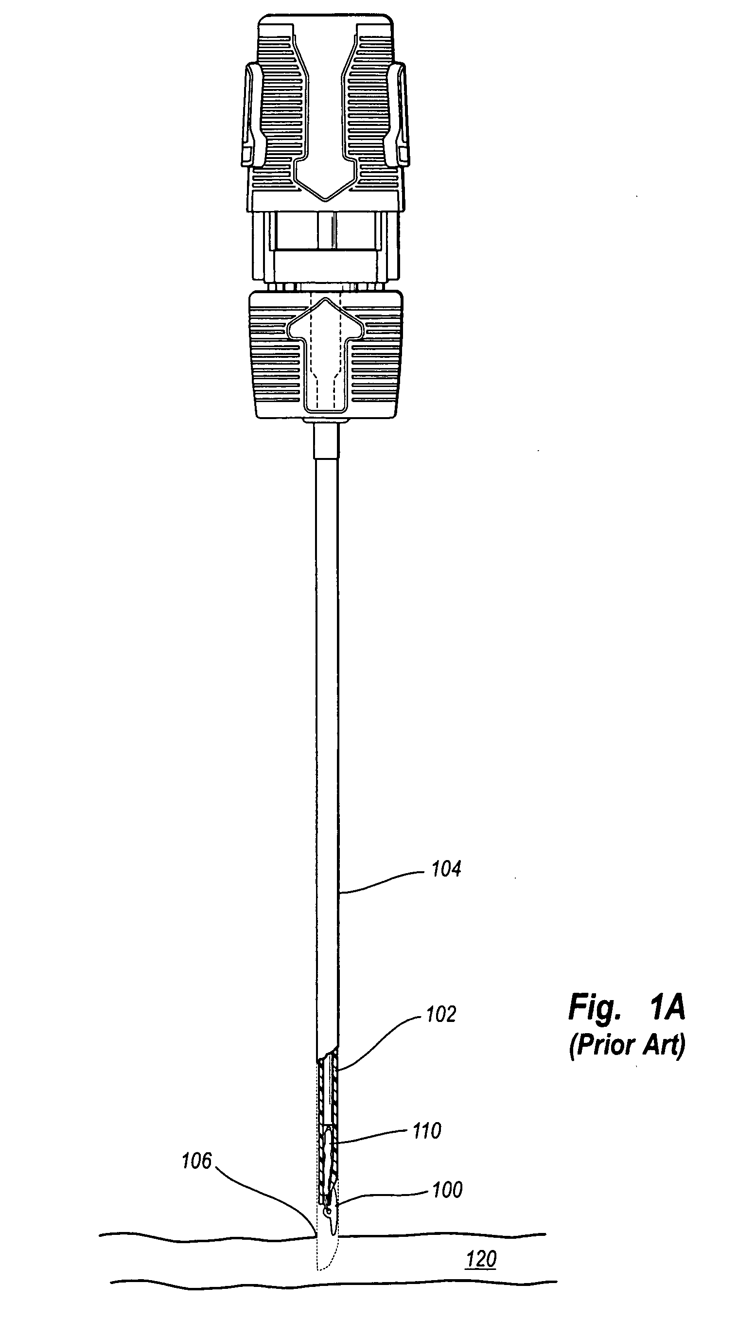
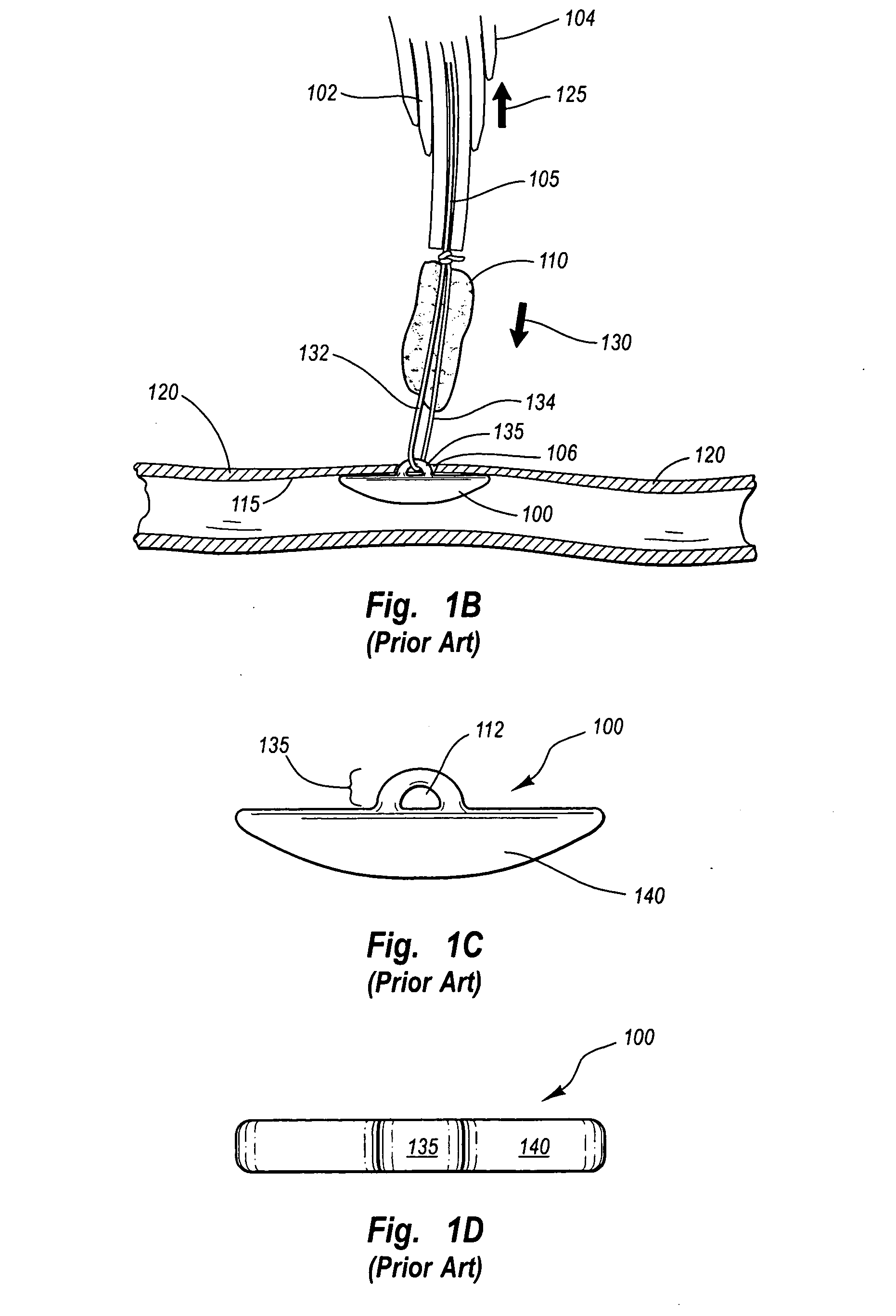
[0024]FIGS. 1A-1F illustrate a prior art tissue puncture closure device with a rotateable anchor. The prior art anchor is designated generally at 100. FIG. 1A illustrates the anchor 100 in a low profile longitudinal configuration resting outside of a carrier tube 102. The anchor 100 is substantially aligned with the carrier tube 102 in the low profile configuration shown. The carrier tube 102 and anchor 100 are shown inserted into an insertion sheath 104, which holds the anchor in its low profile configuration aligned with the carrier tube 102 and is partially inserted through a subcutaneous puncture 106 in an artery 120. In order to seal the puncture 106, the anchor 100 passes through the puncture 106 and the insertion sheath 104, and into the artery 120. When the anchor 100 exits the insertion sheath 104, it is no longer held in the low-profile configuration and it automatically rotates into an expanded transverse configuration as shown in FIG. 1B. The automatic rotation of the an...


PUM


Abstract

The present invention is directed to an anchor that is configured to minimize or overcome lateral rotational moments that could potentially cause the anchor to laterally roll out of its intended position during use. The anchor is shaped to allow for a low profile longitudinal position and expanded transverse position. A device is used to initially insert the anchor in the low profile longitudinal position and then longitudinally rotate the anchor into the expanded transverse position when it is inserted through an incision or opening. The anchor is positioned at an internal portion of the incision or opening such that it seals an internal side of the incision. A sealing plug positioned at an external portion of the incision or opening. The sealing plug and anchor are cinched together with a suture to facilitate rapid healing of the incision or opening.

Description

FIELD OF THE INVENTION [0001] This invention relates to medical devices, and more particularly to a method and apparatus for preventing an anchor from rolling laterally when used with a device for sealing internal tissue incisions or punctures. BACKGROUND OF THE INVENTION [0002] Medical science has advanced tremendously in the last century to include the use of numerous complex internal procedures to treat various human conditions. Many of these procedures require a surgeon to puncture or slice into a portion of the internal human anatomy in order to perform a particular process. For example, many cardiology procedures require accessing the internal portion of a corporeal vessel. After the procedure is completed, the surgeon must repair damage to the internal organ or vessel in order for the patient to properly recover. While it is possible to suture or seal the skin and other organs after the procedure, it is not always possible to suture delicate vessels with the same technique. T...

Claims


Application Information

Patent Timeline
Patent Type & Authority Applications(United States)
IPC IPC(8): A61B17/00A61B17/08A61D1/00
CPCA61B17/0057A61B2017/00778A61B2017/00659A61B2017/00654
Inventor FORSBERG, ANDREW THOMAS
Owner ST JUDE MEDICAL PUERTO RICO BV
Why Eureka
Try Eureka