Check patentability & draft patents in minutes with Patsnap Eureka AI!

Fishing rod holder support stanchion member for holding multiple fishing rod holders in combination with a flush mounted rod holder

a technology of fishing rod holder and support stanchion member, which is applied in fishing, other angling devices, applications, etc., can solve the problems that none of the aforementioned prior art references discloses or teaches the particular design, configuration,

Inactive Publication Date: 2005-05-19
LEGENDZIEWICZ GEORGE
View PDF9 Cites 48 Cited by
  • Summary
  • Abstract
  • Description
  • Claims
  • Application Information

AI Technical Summary

Benefits of technology

[0055] In accordance with the preferred embodiment of the present invention, there is provided a fishing rod holder assembly for holding one or more fishing rod thereto. The fishing rod holder assembly includes a flush mounted rod holder mounted within a gunwale of a boat; a fishing rod holder for holding a fishing rod thereto; and a fishing rod holder support stanchion member having an anchoring post with a horizontal crossbar member connected thereto. The horizontal crossbar member includes a first opposing end and a second opposing end; the first opposing end having a first vertical holding post connected thereto and the second opposing end having a second vertical holding post connected thereto for forming a goalpost configuration thereof. The anchoring post is adaptably mounted within the flush mounted rod holder; and at least one of the fishing rod holders is detachably mounted on the first vertical holding post of the fishing rod holder support stanchion member and another one of the fishing rod holders is detachably mounted on the vertical holding post of the fishing rod holder support stanchion member for forming a fishing rod holder assembly thereof.
[0056] An alternate embodiment of the present invention is also provided to include a fishing rod holder assembly for holding one or more fishing rods thereto. The fishing rod holder assembly includes a flush mounted rod holder mounted within a gunwale of a boat; a fishing rod holder for holding a fishing rod therein; and a modified fishing rod holder support stanchion member having an anchoring post having a pair of angled vertical holding posts connected at a distal end of the anchoring post of the modified fishing rod holder support stanchion member for forming a Y-shaped configuration. The anchoring post being adaptably mounted within the flush mounted rod holder; and at least one of the fishing rod holders is detachably mounted on one of the angled vertical holding posts of the modified fishing rod holder support stanchion member and another one of the fishing rod holders is detachably mounted to the other one of the angled vertical holding posts of the modified fishing rod holder support stanchion member for forming a fishing rod holder assembly thereof.
[0057] Another alternate embodiment of the present invention is additionally provided to include a fishing rod holder assembly for holding one or more fishing rod thereto. The fishing rod holder assembly includes a flush mounted rod holder mounted within a gunwale of a boat; a fishing rod holder for holding a fishing rod therein; and a fishing rod holder support stanchion member having an anchoring post having a horizontal crossbar member connected thereto. The horizontal crossbar member having a first opposing end and a second opposing end; and the first opposing end having a first vertical holding post co...

Problems solved by technology

Additionally, none of the aforementioned prior art references disclose or teach the particular design, configuration or structure of a movable and re-positionable fishing rod holder being mounted to a fishing rod holder support stanchion member in combination with a flush mounted rod holder within a gunwale of a boat.

Method used


Image

  • Fishing rod holder support stanchion member for holding multiple fishing rod holders in combination with a flush mounted rod holder
  • Fishing rod holder support stanchion member for holding multiple fishing rod holders in combination with a flush mounted rod holder
  • Fishing rod holder support stanchion member for holding multiple fishing rod holders in combination with a flush mounted rod holder

Examples


embodiment 10

Preferred Embodiment 10

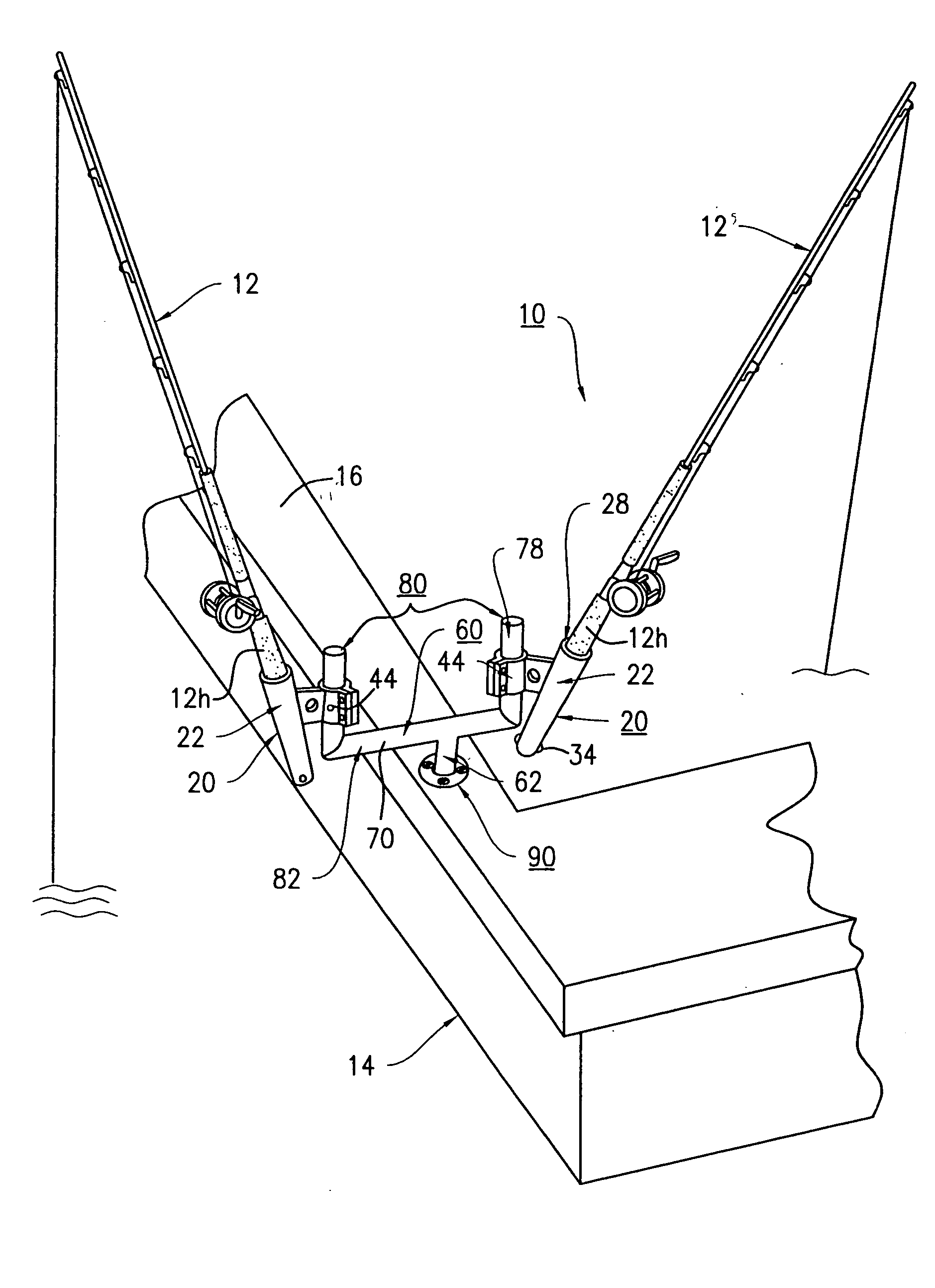
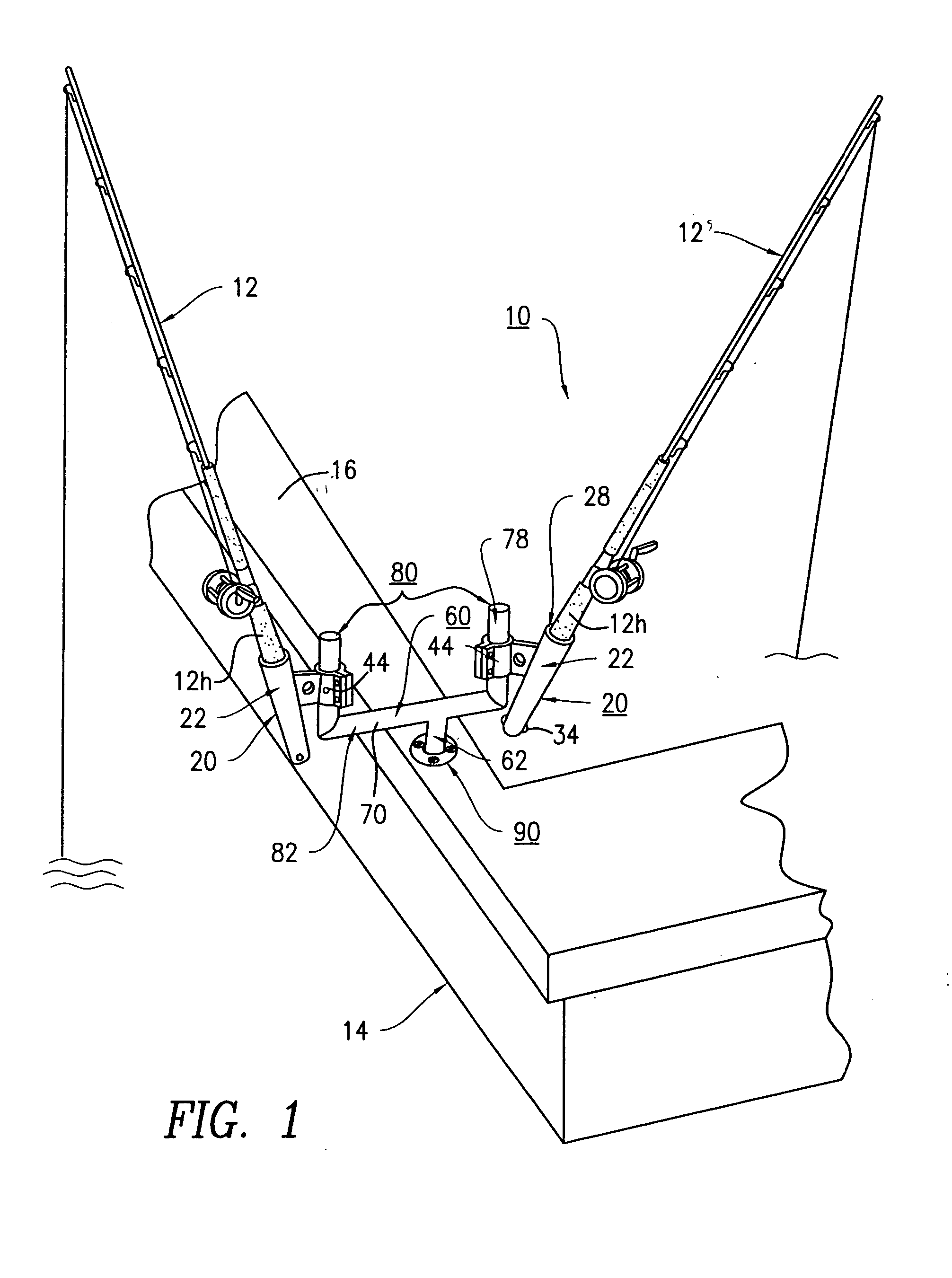
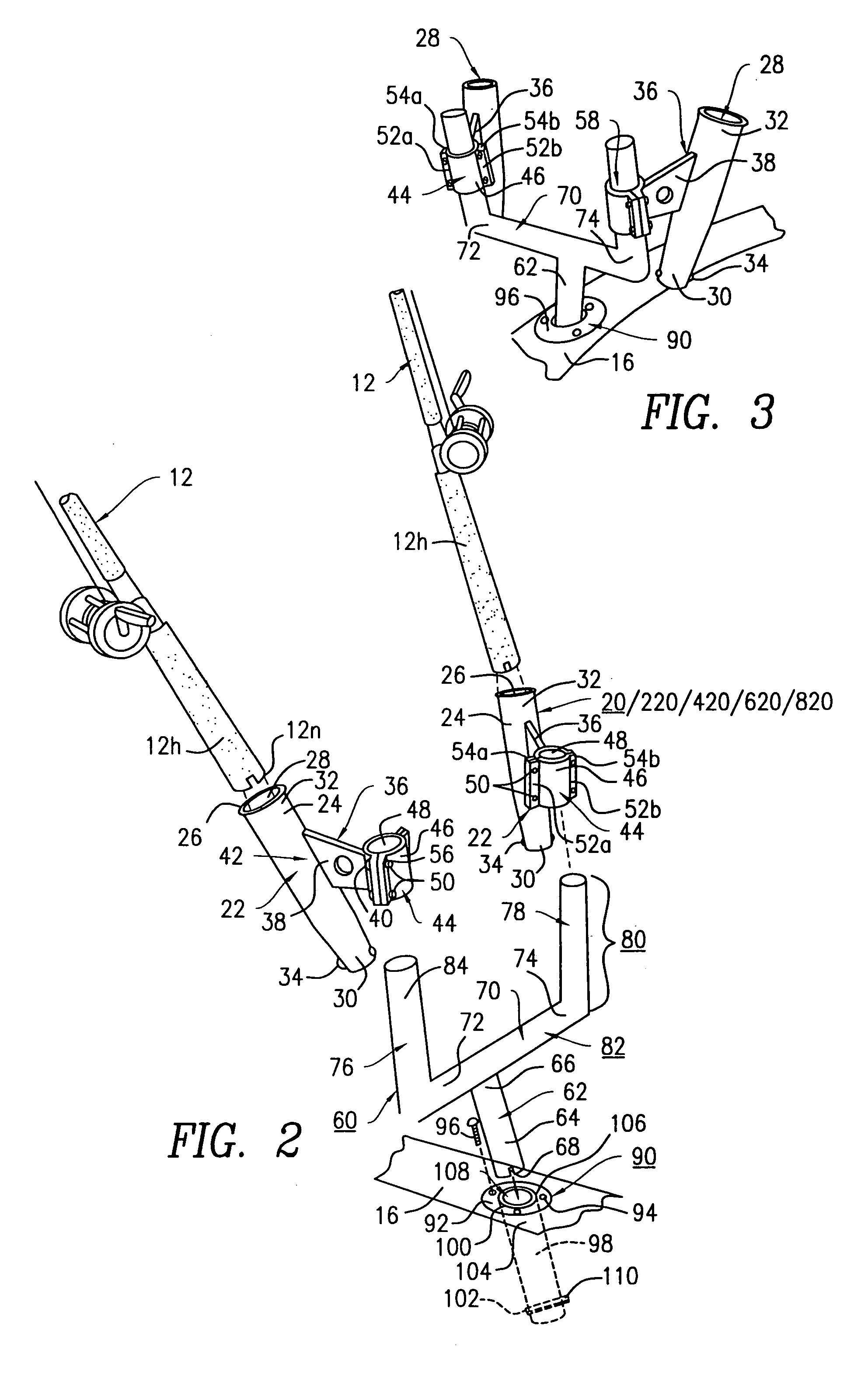
[0100] The fishing rod holder assembly 10 and its component parts of the preferred embodiment of the present invention are represented in detail by FIGS. 1 through 5 of the patent drawings. The fishing rod holder assembly 10 includes one or more fishing rod holders 20 detachably mounted to a fishing rod holder support stanchion member 60 being detachably mounted to a flush mounted rod holder 90 that is mounted to a gunwale 16 of a fishing boat 14.

[0101] The fishing rod holders 20 each including a rod holder member 22 having an outer wall surface 24, an inner wall surface 26 for forming a fishing rod opening 28 for slidably receiving a fishing rod handle 12h of fishing rod 12 therethrough. The rod holder member 22 further includes a proximal end 30 and a distal end 32. The proximal end 30 includes a rod holding pin 34 for securing and receiving a handle locking notch 12n of the fishing rod handle 12h of fishing rod 12, as depicted in FIG. 2 of the drawings, wi...

second alternate embodiment 1000

[0108] The fishing rod holder assembly 1000 and its component parts of the second alternate embodiment are represented in detail by FIGS. 10 through 13 of the patent drawings. Elements illustrated in FIGS. 10 to 13 which correspond to the elements described above with reference to FIGS. 1 to 3 have been designated by corresponding reference numbers increased by one thousand. The second alternate embodiment 1000 is similarly constructed and operates in the same manner as the preferred embodiment 10, unless it is otherwise stated. The fishing rod holder assembly 1000 includes a rotatable fishing rod holder support stanchion member 1060. The rotatable fishing rod holder support stanchion member 1060 includes a U-shaped holding post member 1112 having a horizontal crossbar member 1114 having opposing ends 1116 and 1118. At each of the opposing ends 1116 and 1118 include an integrally connected vertical holding post 1120 and 1122. The horizontal crossbar member 1114 includes a centrally ...

third alternate embodiment 2000

[0110] The fishing rod holder assembly 2000 and its component parts of the third alternate embodiment of the present invention are represented in detail by FIGS. 15 and 16 of the patent drawings. Elements illustrated in FIGS. 15 and 16 which correspond to the elements described above with reference to FIG. 1 to 3 have been designated by corresponding reference numbers increased by two thousand. The third alternate embodiment 2000 is similarly constructed and operates in the same manner as the preferred embodiment 10, unless it is otherwise stated. All aspects of the third alternate embodiment of the fishing rod holder assembly 2000 having fishing rod holder support stanchion member 2060 are exactly the same as the fishing rod holder assembly 10 having the fishing rod holder support stanchion member 60 of the preferred embodiment except that a permanently attached fishing rod holder 2020 is connected to each of the vertical holding posts 2076 and 2078, respectively. Each of the fishi...


PUM


Abstract

A fishing rod holder assembly for holding one or more fishing rods thereto. The fishing rod holder assembly includes two or more fishing rod holders each for holding a fishing rod therein; and a fishing rod holder support stanchion member having an anchoring post and a horizontal crossbar member connected thereto in an offset manner. The horizontal crossbar member includes a first opposing end having a first upwardly extending holding post connected thereto and a second opposing end having a second upwardly extending holding post connected thereto for forming a U-shaped configuration thereof. At least one of the fishing rod holders has a first attachment element mounted on the first upwardly extending holding post of the fishing rod holder support stanchion member and another one of the fishing rod holders has a second attachment element mounted on the second upwardly extending holding post of the fishing rod holder support stanchion member for forming a fishing rod holder assembly.

Description

FIELD OF THE INVENTION [0001] The present invention relates to a fishing rod holder assembly for holding multiple fishing rod holders being mounted to a fishing rod holder support stanchion member in combination with a flush mounted rod holder. More particularly, the fishing rod holder assembly further includes a rotatable, movable and re-positionable fishing rod holder being mounted to a fishing rod holder support stanchion member in combination with a flush mounted rod holder within a gunwale of a boat. BACKGROUND OF THE INVENTION [0002] Sport fishing comes in various formats, for example, a lure or bait is repeatedly cast into the water and retrieved. In those situations, the person doing the fishing must hold the fishing rod at all times. However, in many other fishing forms, it is not necessary or desirable for the fisherman to hold onto the fishing rod at all times. In this fishing format, the bait or lure is cast into the water, either from the shore or from a boat, and is th...

Claims


Application Information

Patent Timeline
IPC IPC(8): A01K97/10
CPCA01K97/10
Inventor LEGENDZIEWICZ, GEORGE
Owner LEGENDZIEWICZ GEORGE
Features
  • R&D
  • Intellectual Property
  • Life Sciences
  • Materials
  • Tech Scout
  • Unparalleled Data Quality
  • Higher Quality Content
  • 60% Fewer Hallucinations
Learn More