Hydroligripcut pliers

a technology of ligripcutting pliers and pliers, which is applied in the field of tools, can solve the problems of limiting the amount of pressure that can be applied, and none can be applied

Inactive Publication Date: 2005-05-19
DEL RIO NORBERTO
View PDF11 Cites 17 Cited by
  • Summary
  • Abstract
  • Description
  • Claims
  • Application Information

AI Technical Summary

Benefits of technology

[0063] The manner of using the Hydroligripcut Pliers is different to that of conventional grip pliers in present use. Namely, one first unscrews the pressure release valve 12 in a counter clock wise direction. Next, you fill the hollow shaft 10 with the recommended fluid. When recommended level is met, you screw the pressure release valve on in a clock wise direction. Now it is ready for use. Next, one positions the jaw 14L and 14AR around the object-as illustrated in (FIG. 4a). One then squeezes down the pressure handle 38 as illustrated in (FIG. 3C). The teeth on the mounting piece of the pressure handle, moves along the teeth of the air push piston 36. Which in turn pushes the air sucked in through the respitory hole 8A. The air being pushed through the intake tuyere 32 as illustrated in (FIG. 3C), pushes up the obturator 46 pushes up the spring 48 which allows the air to pass through the air valve 50. The air that passes through the air valve 50 pushes on the fluid. The fluid pushes the toothed piston rod 30 as illustrated in (FIG. 3C), to the distal end of the hollow shaft 10. By pushing the toothed piston rod 30 the teeth of the toothed piston rod 30 grip the teeth of the jaws 14L and 14AR. With the movement of the teeth the jaws 14L and 14AR in turn close around the

Problems solved by technology

Only manual pressure can be applied which also limits the amount of pressure that can be

Method used


Image

  • Hydroligripcut pliers
  • Hydroligripcut pliers
  • Hydroligripcut pliers

Examples


Embodiment Construction

—FIGS. 1, 2, 2A TO 2J—PREFERRED EMBODIMENT

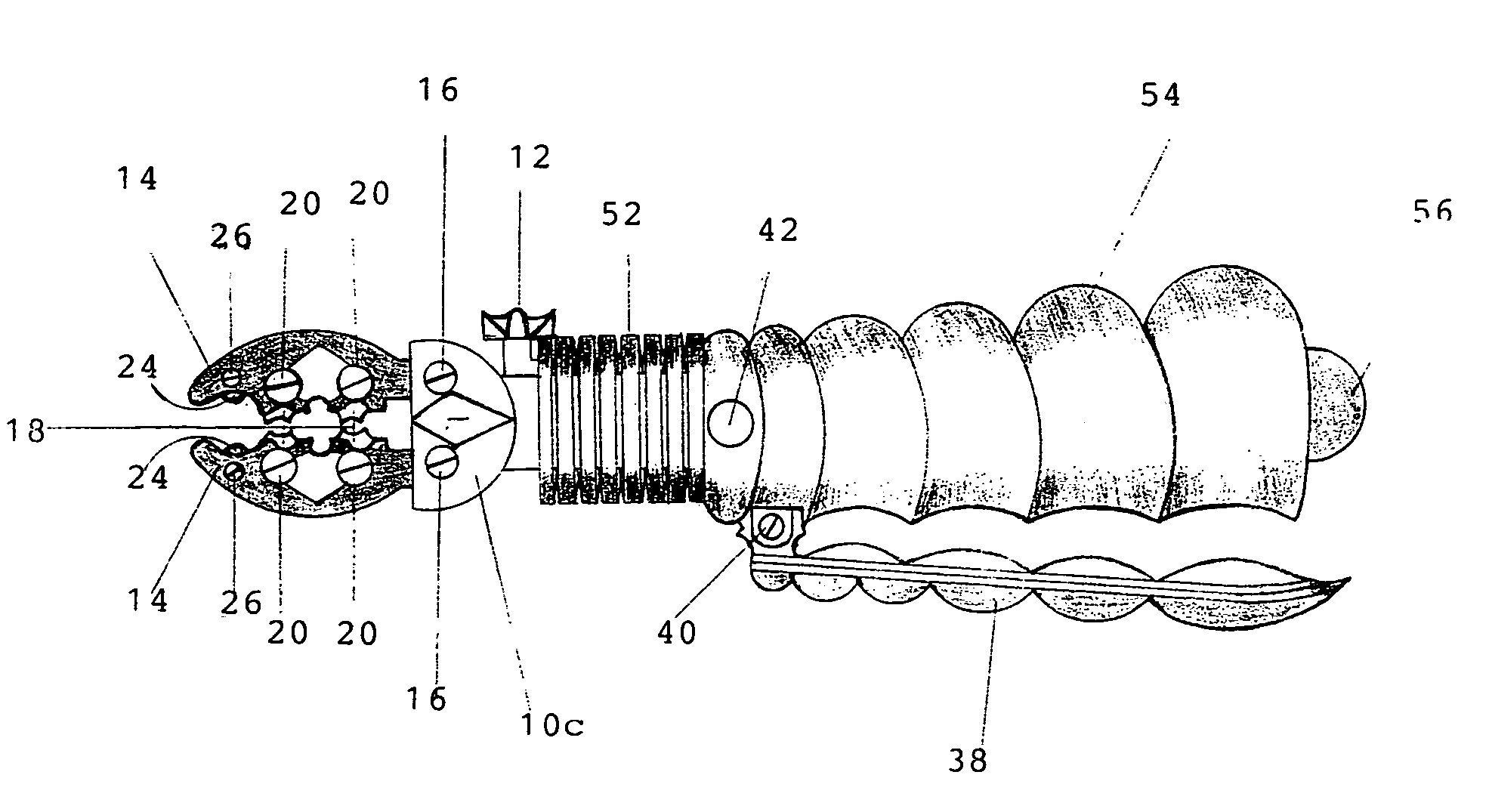
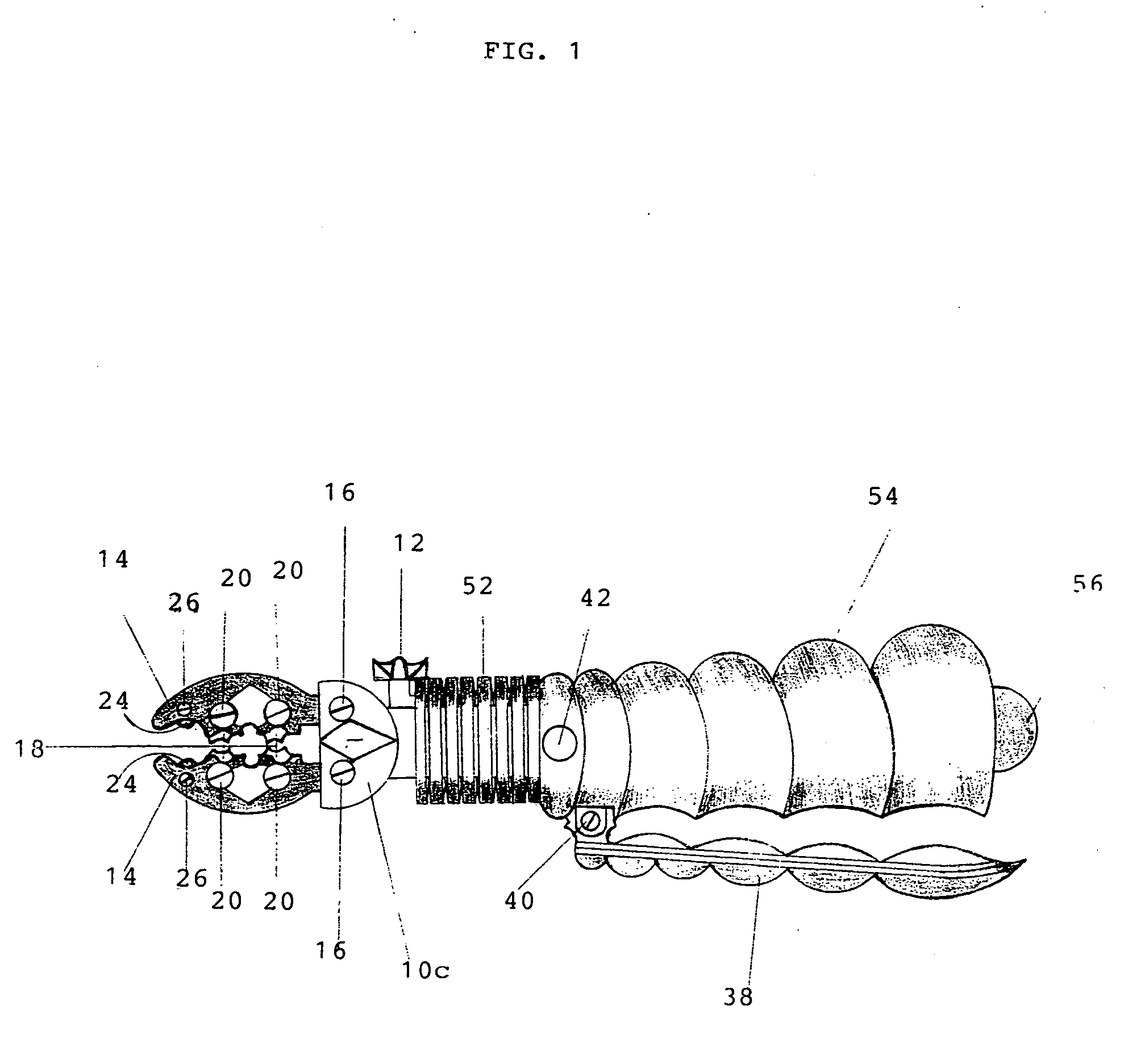
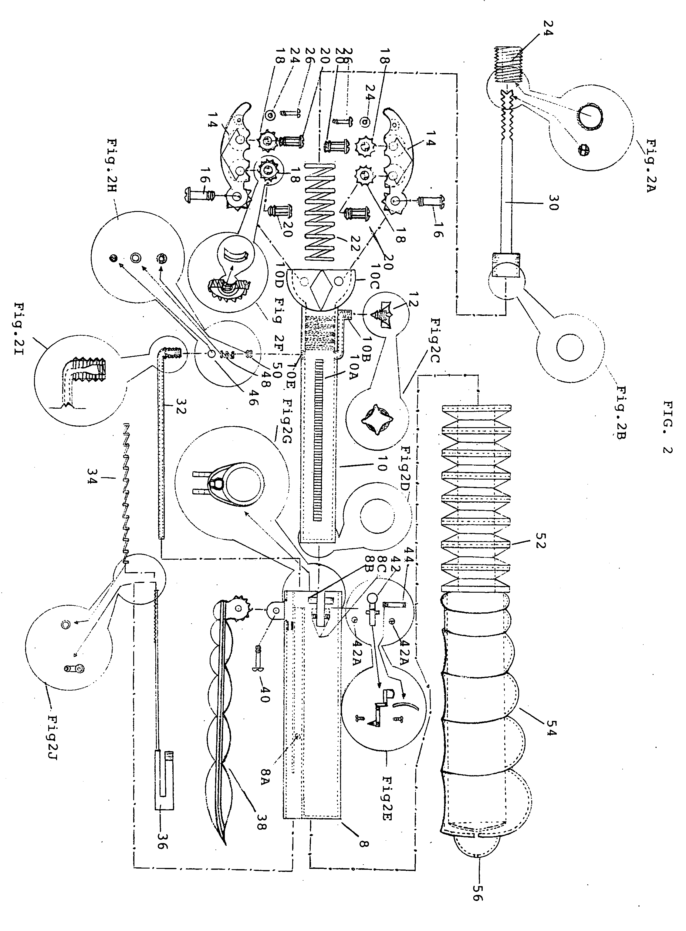
[0061] A preferred embodiment of the present invention is illustrated in FIG. 1. FIG. 2 shows an (exploded view) of the basic version of my tool. My tool has a main housing 8 which is equipped with a respitory hole 8A. The main housing 8 accommodates an intake tuyere 32, which slides in through the middle slot as illustrated in (FIG. 2G). The main housing 8 also has a spring groove 8B, which accommodates a curved flat spring 44. Also on the main housing 8 is a grooved bore 8C which accommodates an extension push button 42. You place the curved flat spring 44 in the spring groove 8b. You then insert the extension push button 42 in the grooved bore 8c, then slide in toward distal end. Which is then anchored in place with a pair of extension push button fastening screws 42A. A spring 34 is used in conjunction with an air pump piston 36, which is equipped with a toothed rod. The toothed rod of the air pump piston 36 slides in through the spring ...


PUM

PropertyMeasurementUnit
Volumeaaaaaaaaaa
Currentaaaaaaaaaa
Torqueaaaaaaaaaa

Abstract

A comfortable and easy-to-use tool and of the type having a hollow shaft (10), housing a hydraulic system comprising of a spring (22), a toothed piston rod (30), a sealing bolt (28), an intake tuyere (32), and a pressure release valve (12). That in conjunction with the jaw's 14L and 14AR, facilitate the tightening and loosening of bolts, screws, nuts, etc. . . . And to finalize, the cutting of pipes and certain objects. In addition, an air comfort handgrip handle (54) with the use of the air comfort hand grip (56) adds continuous comfort while using the tool. An extendable neck comprising of a system with an extension push button (42), an extension push button fastening screw (42A) and a curved flat spring (44) supply a means for application of more torque.

Description

CROSS-REFERENCE TO RELATED APPLICATIONS [0001] Not Applicable FEDERALLY SPONSORED RESEARCH [0002] Not Applicable SEQUENCE LISTING OR PROGRAM [0003] Not Applicable BACKGROUND OF THE INVENTION [0004] 1. Field of Invention [0005] This invention relates to tools, specially to an improved pair of grip pliers. [0006] 2. Background of the Invention [0007] Originally basic grip pliers come in 3 sizes 5″, 7″, and 10″ and are made with one fixed jaw and a movable jaw, limiting the amount of pressure that can be applied. They manually adjust to size of the object to be tightened or loosened. Only manual pressure can be applied which also limits the amount of pressure that can be applied. If more torque is needed none can be applied due to the length of the grip pliers. When tightening or loosening, once extent of positive motion is met, one has to release pressure of grip due to the absence of negative motion and reapply it. This invention brings solutions to these disadvantages. Objects and...

Claims


Application Information

Patent Timeline
IPC IPC(8): B23D17/06B25B7/12B26D5/12
CPCB23D17/06B23D21/06B23D29/002B26D5/12B25B7/126B26D3/169B25B7/12
Inventor DEL RIO, NORBERTO
Owner DEL RIO NORBERTO
Why Eureka
Try Eureka