Camera head for fast reproduction of a vaccum uv spectrometer spectrum

a spectrometer and camera head technology, applied in the field of camera head for fast reproduction of vaccum uv spectrometer spectrum, can solve the problem of insufficient gain, achieve the effect of increasing the efficiency of the complete system, increasing the height of the slit, and increasing the deterioration of wavelength resolution

a spectrometer and camera head technology, applied in the field of camera head for fast reproduction of vaccum uv spectrometer spectrum, can solve the problem of insufficient gain, achieve the effect of increasing the efficiency of the complete system, increasing the height of the slit, and increasing the deterioration of wavelength resolution

US20050105086A1Inactive Publication Date: 2005-05-19FORSCHUNGSZENTRUM JULICH GMBH

Image

  • Camera head for fast reproduction of a vaccum uv spectrometer spectrum
  • Camera head for fast reproduction of a vaccum uv spectrometer spectrum
  • Camera head for fast reproduction of a vaccum uv spectrometer spectrum

Examples


Embodiment Construction

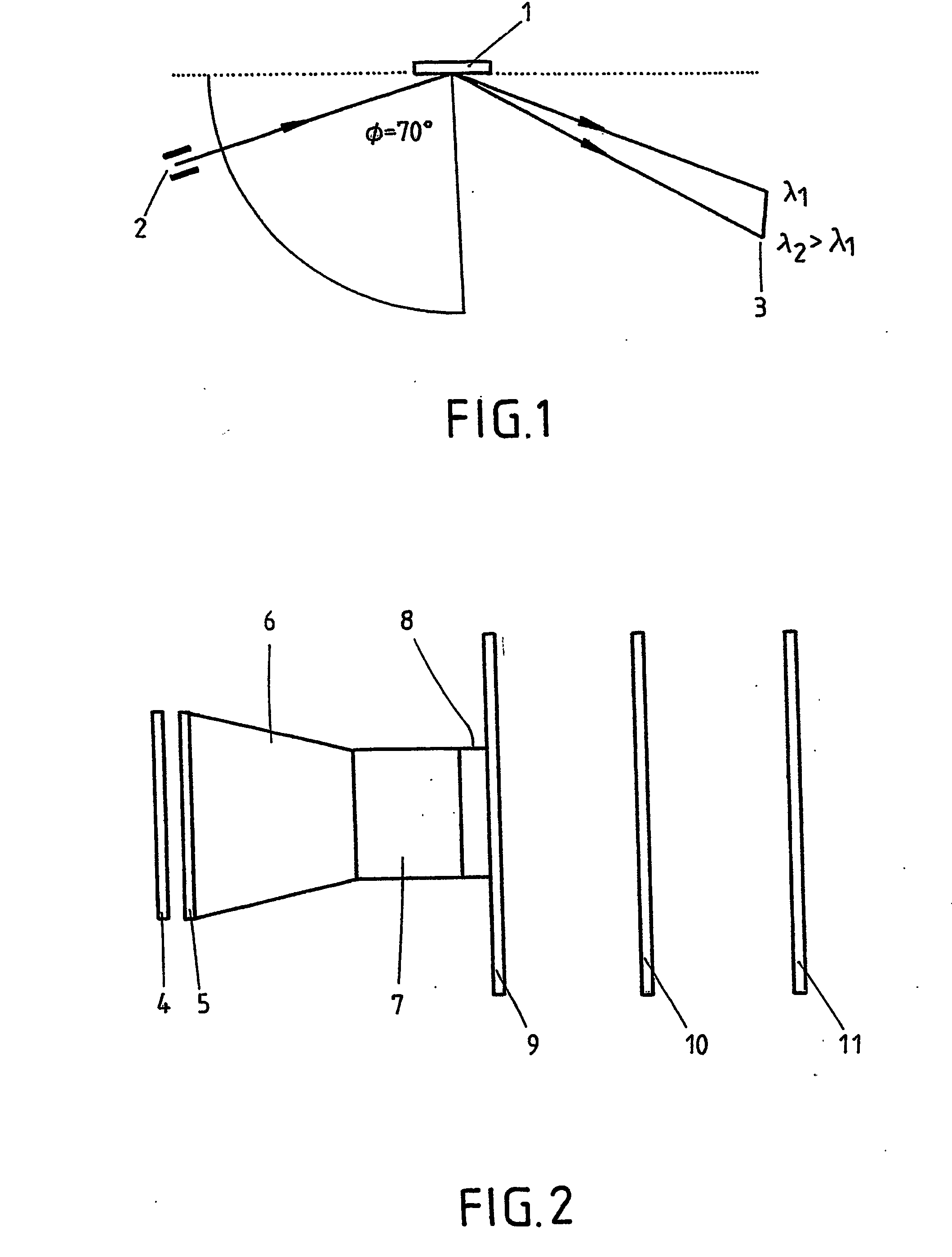
[0031] In one embodiment, a fiber optic cross-section converter (with a ratio of, for example 40 / 25) is mounted between the (phosphor) screen (width e.g. approx. 40 mm) and the sensor which makes the image (spectrum) smaller in the exemplary case. In this manner, an adjustment to the geometrical measurements of the sensor can be carried out. This fiber optic image is considerably more intense compared to an image created by means of lenses, and hence, is to be preferred for this application.

[0032] Since the permitted output intensity of the open MCP detector, modulated up to its linearity limit, does not suffice, as a rule, to modulate sensor S3904 (full capacity 25 pC) sufficiently, in a further embodiment, an image intensifier of the first generation (“diode”) with a fiber optic coupling is interposed between the fiber optic cross-section converter and sensor that can bring about an additional linear light intensification by a factor of 10-15 without significant losses in spatial...


PUM


Abstract

The invention relates to an apparatus comprising a spectrometer, means for the spatially-resolving conversion into charge of light exiting the spectrometer, an integrator circuit for the spatially-resolving integration of the charge, as well as means for displaying the charge that is integrated dependent on the position. The integrator circuit is assembled from discrete components. Thus, the transport of plasma impurities can be properly measured.

Description

FIELD OF THE INVENTION [0001] The invention relates to an apparatus for measuring the transport time of impurity particles in a plasma, comprising a spectrometer and a line-scan camera. The spectrometer has an entrance slit. The spectral lines emitted by the impurity particles fall through the entrance slit. Then, the spectral lines fall onto a diffraction grating. Depending on wavelength, the spectral lines are reflected at different angles. The split light signals leaving the spectrometer are collected by a spatially-resolving line-scan camera. The transport time is calculated from the measurement information thus obtained. During operation, the spectrometer is located in a vacuum atmosphere. BACKGROUND OF THE INVENTION [0002] For the experimental examination of the radial transport of plasma impurities, i.a. a small amount of a plasma impurity is introduced into the plasma at the plasma edge, and then, the development in time of the spectral lines of different degrees of ionizati...

Claims


Application Information

Patent Timeline
19 May 2005
Publication
US20050105086A1
IPC
G01J3/443; G01J1/02; G01J1/42; G01J1/44; G01J3/28; G01J3/36
CPC
G01J1/58; G01J3/2889; G01J3/2803
Inventors
BIEL, WOLFGANG; SCHOLL, ALFRED