User interface for external charger for implantable medical device

a medical device and user interface technology, applied in the field of implantable medical devices, can solve the problems of inconvenient continuous coupling of patients to external power for therapy, disadvantageous electric wires perforating the skin, and high risk of infection

Active Publication Date: 2005-05-26
MEDTRONIC INC
View PDF56 Cites 146 Cited by
  • Summary
  • Abstract
  • Description
  • Claims
  • Application Information

AI Technical Summary

Benefits of technology

[0008] In an embodiment, the present invention provides an implantable medical device system. An implantable medical device provides a therapeutic output to a patient. An external patient control unit can be operatively coupled via telemetry with the implantable medical device allowing the patient to control the therapeutic output of the implantable medical device. An external energy transfer unit can be operatively coupled to the implantable medical device to transcutaneously transfer energy to the implantable medical device. The externa

Problems solved by technology

Having electrical wires which perforate the skin is disadvantageous due, in part, to the risk of infection.
Further, continuously coupling patients to an external power for therapy is, at least, a large inconvenience.
However, such single cell

Method used


Image

  • User interface for external charger for implantable medical device
  • User interface for external charger for implantable medical device
  • User interface for external charger for implantable medical device

Examples


Embodiment Construction

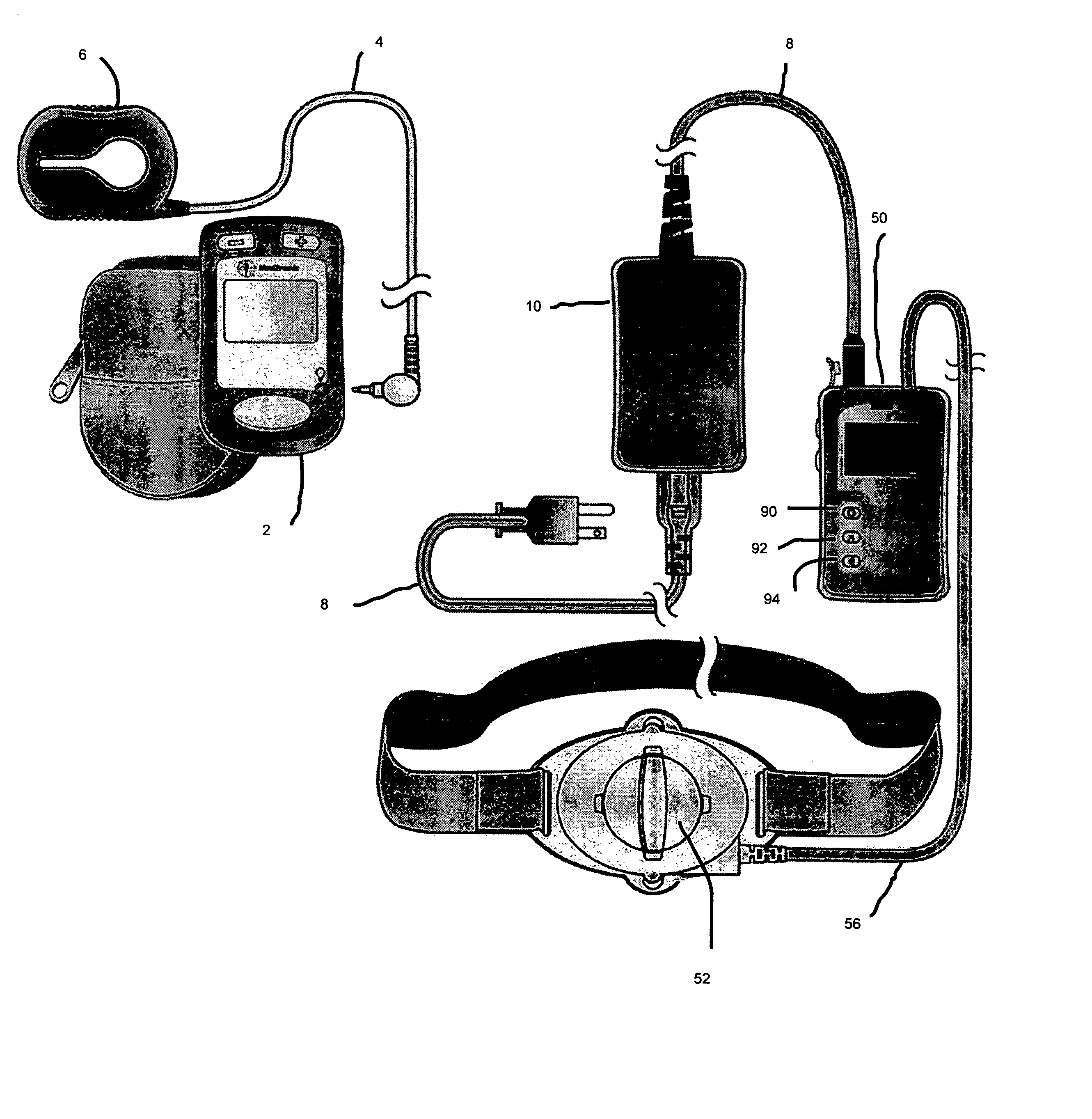
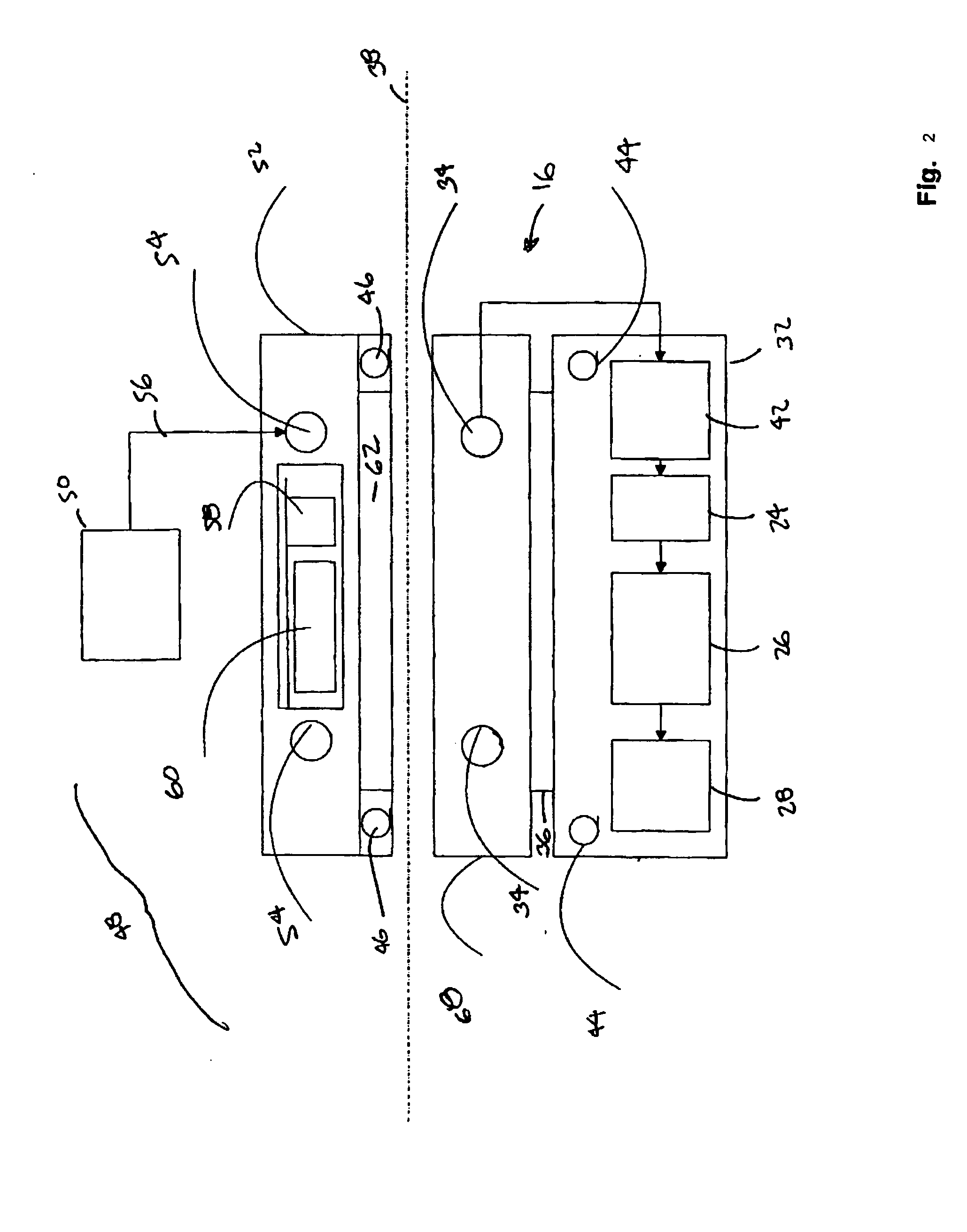
[0058] In FIG. 1, external programming unit 2 is attachable via cord 4 to an external telemetry coil 6. External programming unit 2 can program operations implantable medical device 16 (FIG. 2) in a conventional manner using external telemetry coil 6. External antenna 52 is attachable via cord 56 to external charging device 48 is inductively transfer power to implantable medical device 16 when external antenna 52 is placed in proximity of a secondary coil 24 associated with implantable medical device 16. External charging device 48 receives AC power from cord 8 through transformer 10. External antenna 52 can be held in position on patient 18 with belt 12.

[0059]FIG. 2 illustrates an embodiment of implantable medical device 16 situated under cutaneous boundary 38. Charging regulation and therapy control is conventional. Implantable medical device 16 also has internal telemetry coil 44 configured in conventional manner to communicate through external telemetry coil 46 to an external p...


PUM


Abstract

User interface for external power source, recharger, for an implantable medical device. At least some of patient controls and display icons of an energy transfer unit are common with at least some of the patient controls and the display icons of a patient control unit. An energy transfer unit is operable by the patient with less than three operative controls to control energy transfer from the external energy transfer unit to the implantable medical device. An external antenna having a primary coil can inductively transfer energy to a secondary coil of the implantable medical device when the external antenna is externally placed in proximity of the secondary coil. An energy transfer unit has an external telemetry coil allowing the energy transfer unit to communicate with the implantable medical device through the internal telemetry coil in order to at least partially control the therapeutic output of the implantable medical device.

Description

RELATED APPLICATIONS [0001] This application is claims priority to U.S. Provisional Application Ser. No. 60 / 508,198, filed Oct. 2, 2003, entitled User Interface for External Charger for Implantable Medical Device, and from U.S. Provisional Application Ser. No. 60 / 513,732, filed Oct. 23, 2003, entitled User Interface for External Charger for Implantable Medical Device. The entire contents of both of the foregoing applications are hereby incorporated by reference.FIELD OF THE INVENTION [0002] This invention relates to implantable medical devices and, in particular, to energy transfer devices, systems and methods for implantable medical devices. BACKGROUND OF THE INVENTION [0003] Implantable medical devices for producing a therapeutic result in a patient are well known. Examples of such implantable medical devices include implantable drug infusion pumps, implantable neurostimulators, implantable cardioverters, implantable cardiac pacemakers, implantable defibrillators and cochlear impl...

Claims


Application Information

Patent Timeline
IPC IPC(8): A61N1/08A61N1/372A61N1/378
CPCA61N1/3787
Inventor BAUHAHN, RUTH E.SCHOMMER, MARK E.
Owner MEDTRONIC INC
Why Eureka
Try Eureka