External power source for an implantable medical device having an adjustable carrier frequency and system and method related therefore

a technology of external power source and medical device, which is applied in the field of implantable medical devices, can solve the problems of disadvantageous electric wires perforating the skin, large inconvenience in continuously coupling patients to external power for therapy, and at least large risk of infection, and achieve the effect of increasing the energy transfer efficiency of the tuned inductive charging circui

Active Publication Date: 2012-03-20
MEDTRONIC INC
View PDF52 Cites 353 Cited by
  • Summary
  • Abstract
  • Description
  • Claims
  • Application Information

AI Technical Summary

Benefits of technology

[0020]Generally, the carrier frequency of a transcutaneous device is matched to a presumed resonant frequency established for a tuned inductive charging circuit. However, a theoretical or even an actual resonant frequency of a tuned inductive charging circuit can and typically does change as external charging components are moved relative to internal charging components and due to other surrounding factors. For example, the proximity of large metal, or otherwise conductive, objects near the tuned inductive charging circuit may have a significant effect on the resonant frequency. This result may be that a presumed or an initial resonant frequency of a tuned inductive charging circuit may differ significantly from the actual resonant frequency encountered in a real life environment and / or an initial resonant frequency may change as positioning changes and / or the environment of the tuned inductive charging circuit changes. An inductive charging circuit being driven at a certain carrier frequency which differs from the actual resonant frequency of the tuned inductive charging circuit typically will have the best possible efficiency.
[0021]The efficiency of transcutaneous inductive energy transfer is directly related to how well the carrier frequency driving the tuned inductive charging circuit matches the actual environment encountered by the tuned inductive charging circuit. By varying the carrier frequency, if necessary, to match the current environment of the tuned inductive charging circuit can increase the efficiency of energy transfer.

Problems solved by technology

Having electrical wires which perforate the skin is disadvantageous due, in part, to the risk of infection.
Further, continuously coupling patients to an external power for therapy is, at least, a large inconvenience.
However, such single cell batteries usually do not supply the lasting power required to perform new therapies in newer implantable medical devices.
This is not desirable due to the need to explant and re-implant the implantable medical device or a portion of the device.
The sinusoidal waveform reduces eddy current effects in the implanted device which detrimentally increases the temperature of the implanted device.
First, the inductive coupling, while inductively inducing a current in the secondary coil, also has a tendency to heat surrounding components and tissue.
The amount of heating of surrounding tissue, if excessive, can be deleterious.
Since heating of surrounding tissue is limited, so also is the amount of energy transfer which can be accomplished per unit time.
This attachment may impair the patient's mobility and limit the patient's comfort.
Third, amount of charging, or recharging, can be limited by the amount of time required for charging, or recharging.
Since the patient is typically inconvenienced during such charging, or recharging, there is a practical limit on the amount of time during which charging, or recharging, should occur.
Hence, the size of the internal power source can be effectively limited by the amount of energy which can be transferred within the amount of charging time.
Prior art implantable medical devices, external power sources, systems and methods have not always provided the best possible benefit leading to efficiency of energy transfer and patient comfort.

Method used


Image

  • External power source for an implantable medical device having an adjustable carrier frequency and system and method related therefore
  • External power source for an implantable medical device having an adjustable carrier frequency and system and method related therefore
  • External power source for an implantable medical device having an adjustable carrier frequency and system and method related therefore

Examples


Embodiment Construction

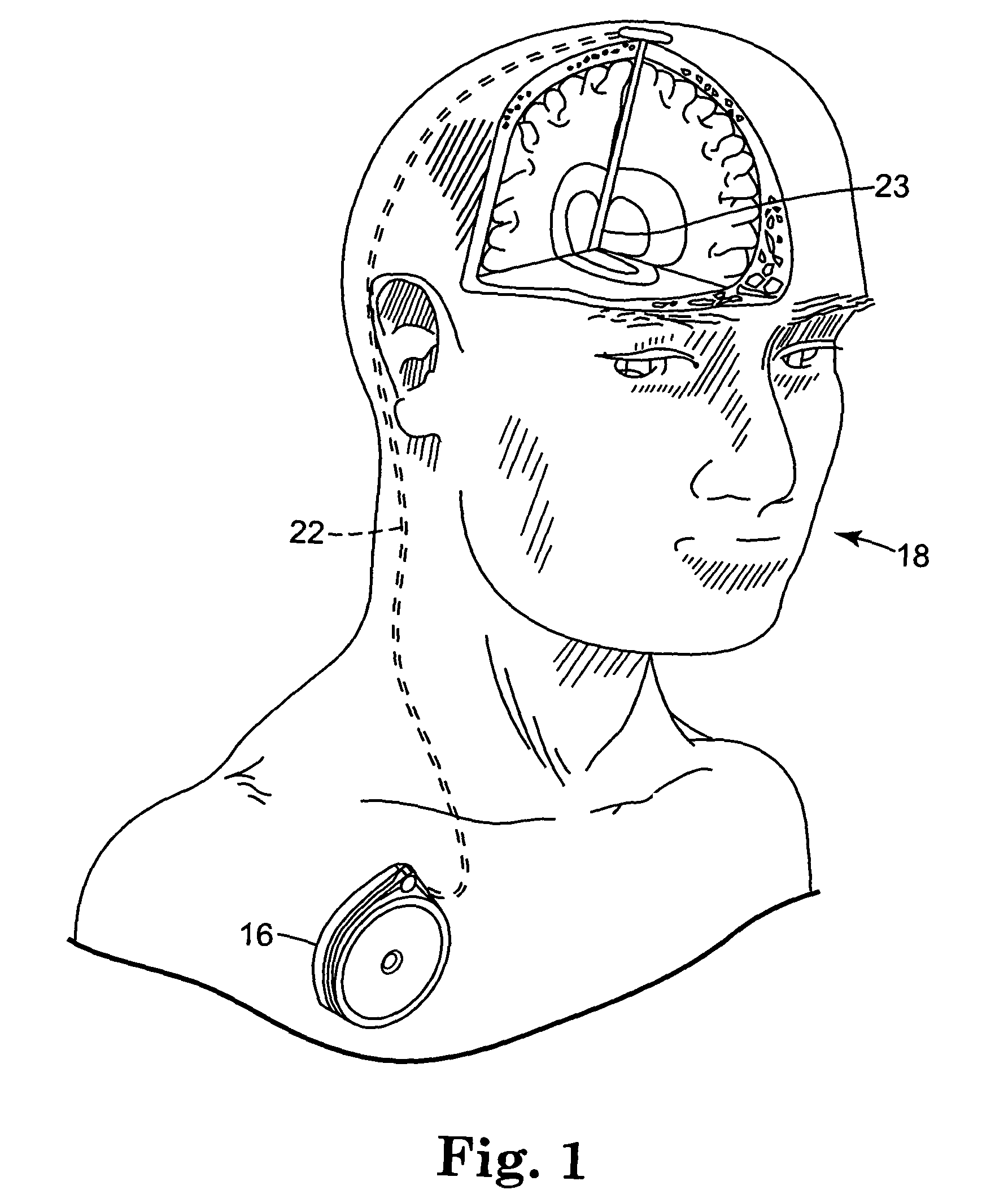
[0061]FIG. 1 shows implantable medical device 16, for example, a drug pump, implanted in patient 18. The implantable medical device 16 is typically implanted by a surgeon in a sterile surgical procedure performed under local, regional, or general anesthesia. Before implanting the medical device 16, a catheter 22 is typically implanted with the distal end position at a desired therapeutic delivery site 23 and the proximal end tunneled under the skin to the location where the medical device 16 is to be implanted. Implantable medical device 16 is generally implanted subcutaneously at depths, depending upon application and device 16, of from 1 centimeter (0.4 inches) to 2.5 centimeters (1 inch) where there is sufficient tissue to support the implanted system. Once medical device 16 is implanted into the patient 18, the incision can be sutured closed and medical device 16 can begin operation.

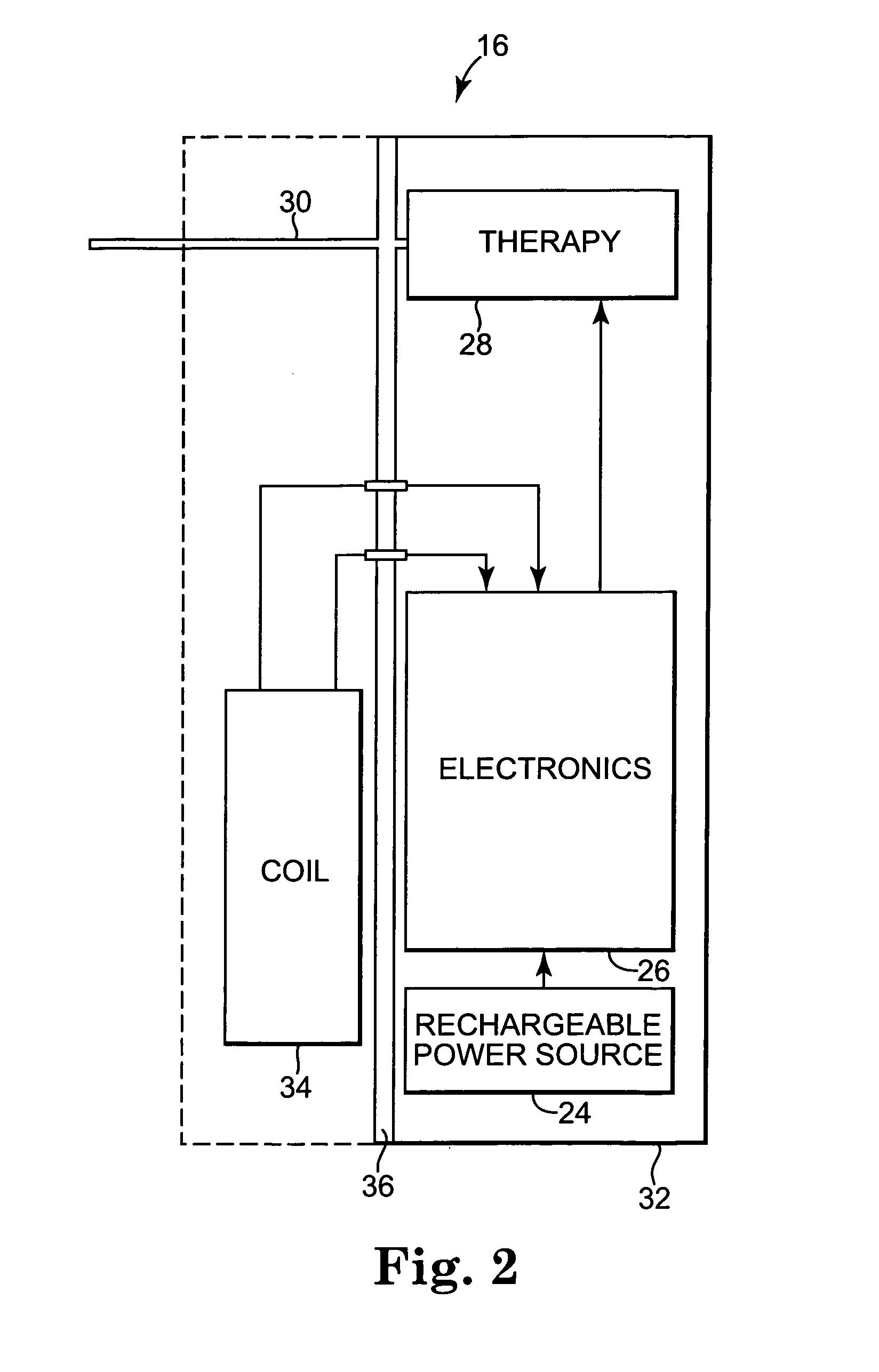
[0062]Implantable medical device 16 operates to infuse a therapeutic substance into patient 18. I...


PUM


Abstract

A transcutaneous energy transfer system, transcutaneous charging system, external power source, external charger and methods of transcutaneous energy transfer and charging for an implantable medical device and an external power source / charger. The implantable medical device has a secondary coil adapted to be inductively energized by an external primary coil at a carrier frequency. The external power source / charger has a primary coil and circuitry capable of inductively energizing the secondary coil by driving the primary coil at a carrier frequency adjusted to the resonant frequency to match a resonant frequency of the tuned inductive charging circuit, to minimize the impedance of the tuned inductive charging circuit or to increase the efficiency of energy transfer.

Description

RELATED APPLICATION[0001]This application claims priority to provisional U.S. Application Ser. No. 60 / 508,176, filed Oct. 2, 2003.FIELD OF THE INVENTION[0002]This invention relates to implantable medical devices and, in particular, to energy transfer devices, systems and methods for implantable medical devices.BACKGROUND OF THE INVENTION[0003]Implantable medical devices for producing a therapeutic result in a patient are well known. Examples of such implantable medical devices include implantable drug infusion pumps, implantable neurostimulators, implantable cardioverters, implantable cardiac pacemakers, implantable defibrillators and cochlear implants. Of course, it is recognized that other implantable medical devices are envisioned which utilize energy delivered or transferred from an external device.[0004]A common element in all of these implantable medical devices is the need for electrical power in the implanted medical device. The implanted medical device requires electrical p...

Claims


Application Information

Patent Timeline
Patent Type & Authority Patents(United States)
IPC IPC(8): A61N1/08A61N1/378
CPCA61N1/3787
Inventor OLSON, DAVID P.SCHMELING, ANDREW L.NELSON, STEVEN J.
Owner MEDTRONIC INC
Why Eureka
Try Eureka