Suppression of interference in digital frequency synthesis, more particularly in a time reference of a navigation signal transmitting device

a technology of digital frequency synthesis and time reference, which is applied in the direction of digital transmission, generating/distributing signals, instruments, etc., can solve the problems of only inadequate suppression of quantization errors, significant interference lines remain in the output spectrum of the synthesizer, and devices for direct digital frequency synthesis

Inactive Publication Date: 2005-06-09
AIRBUS DEFENCE & SPACE
View PDF38 Cites 11 Cited by
  • Summary
  • Abstract
  • Description
  • Claims
  • Application Information

AI Technical Summary

Benefits of technology

[0010] However, the prior art devices for direct digital frequency synthesis have the disadvantage that the quantization errors are only inadequately suppressed, and moreover significant interference lines remain in the output spectrum of the synthesizer. Consequently, the object of the present invention is to provide an improved method for direct digital frequency synthesis.
[0012] The present invention comprises an arrangement for digital frequency synthesis with a device for phase quantization and a device for amplitude quantization, based on a reference clock and a phase increment value, wherein the device for phase quantization is followed in the signal path by a device for noise shaping of the phase. In accordance with the invention, provision is now made that a device for noise shaping of the amplitude is provided in addition, which follows the device for amplitude quantization in the signal path. This makes it possible to achieve the result that, in addition to the errors resulting from the phase quantization, additional errors resulting from the amplitude quantization are also suppressed. These errors from amplitude quantization arise due to the limited bit resolution of the digital-to-analog converter (D / A converter). These errors, too, can be suppressed by noise shaping. With the aid of the invention, the interference energy of the interference lines (spurs) for both types of errors can be displaced to higher frequencies outside the useful bandwidth of the synthesizer. This knowledge is not known from the prior art to date. In the invention, the errors, or at least an adequate portion of the errors, arising from phase quantization and amplitude quantization are fed to the device for noise shaping.
[0016] A special application of the present invention relates to a time reference device with a reference frequency for a navigation signal transmitting device. Such a time reference device generates a reference frequency that serves as a basis for time information in the navigation signals which are transmitted by the navigation signal transmitting device and are received by corresponding navigation terminals. Navigation satellites in satellite navigation systems such as GPS or Galileo are an example of such navigation signal transmitting devices; another example is terrestrial navigation signal transmitting devices, which either augment a satellite navigation system to ensure the illumination of certain regions that are shadowed as seen from the satellite, or increase the accuracy of the satellite navigation system (e.g., differential GPS). Especially in navigation satellites, atomic clocks are used in the time reference devices. A reference frequency for the navigation signal transmitting device is generated based on the signals from the atomic clocks. Especially in this application, quantization errors are very critical, since they can directly or indirectly impair the time information in the navigation signal and thus the accuracy of position finding by the navigation terminals.

Problems solved by technology

However, the prior art devices for direct digital frequency synthesis have the disadvantage that the quantization errors are only inadequately suppressed, and moreover significant interference lines remain in the output spectrum of the synthesizer.
These errors from amplitude quantization arise due to the limited bit resolution of the digital-to-analog converter (D / A converter).

Method used


Image

  • Suppression of interference in digital frequency synthesis, more particularly in a time reference of a navigation signal transmitting device
  • Suppression of interference in digital frequency synthesis, more particularly in a time reference of a navigation signal transmitting device
  • Suppression of interference in digital frequency synthesis, more particularly in a time reference of a navigation signal transmitting device

Examples


Embodiment Construction

[0024] The particulars shown herein are by way of example and for purposes of illustrative discussion of the embodiments of the present invention only and are presented in the cause of providing what is believed to be the most useful and readily understood description of the principles and conceptual aspects of the present invention. In this regard, no attempt is made to show structural details of the present invention in more detail than is necessary for the fundamental understanding of the present invention, the description taken with the drawings making apparent to those skilled in the art how the several forms of the present invention may be embodied in practice.

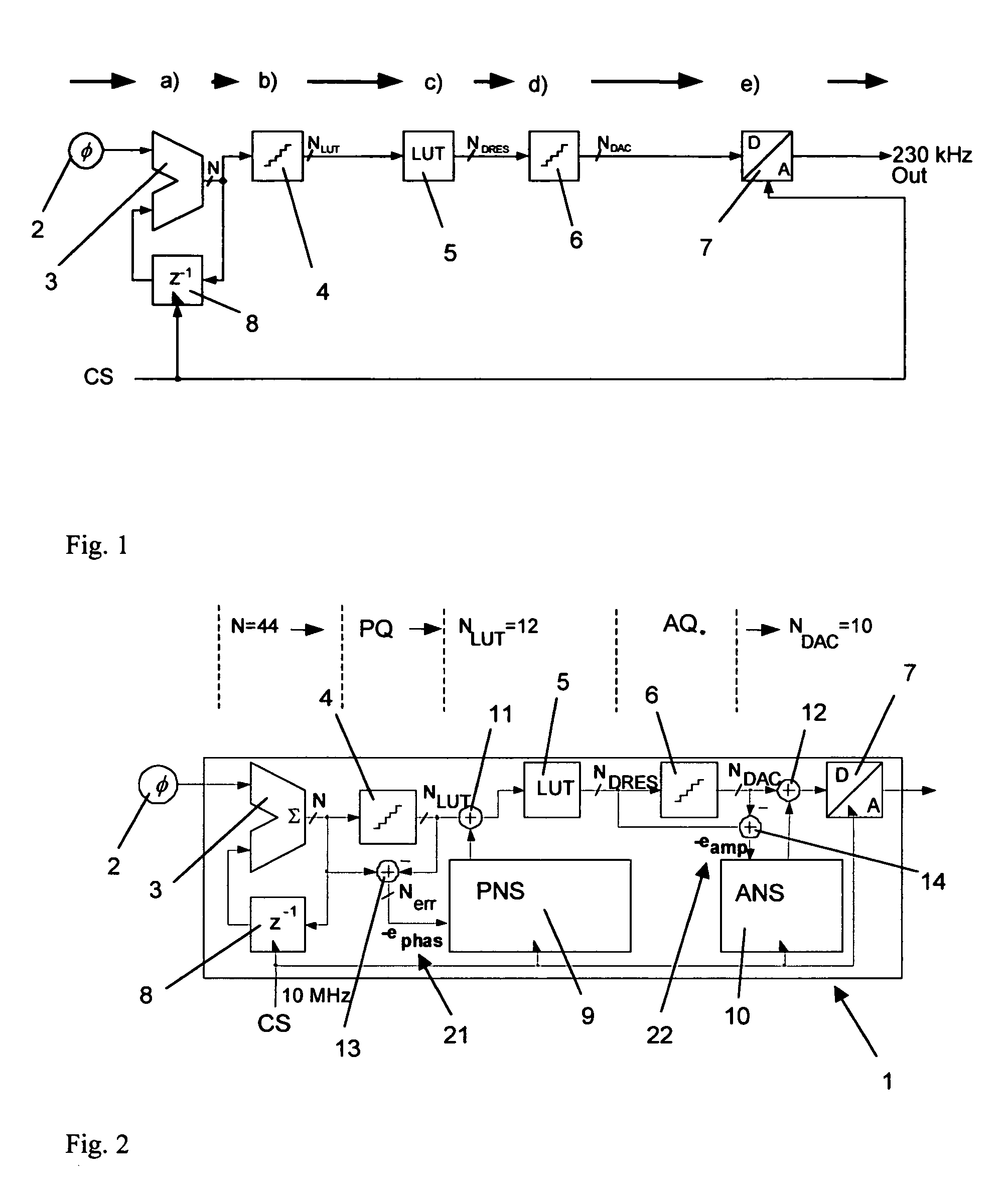
[0025]FIG. 1 shows the principle of digital frequency synthesis in accordance with prior art. The direct digital frequency synthesis is based on an accumulator 3 that is incremented by a phase value □ at every system clock of a clock signal (clock signal CS), and on an inverter 8. The phase value □ is generated by a sui...


PUM


Abstract

Described is an arrangement for digital frequency synthesis with a device for phase quantization and a device for amplitude quantization, based on a reference clock and a phase increment value, wherein the device for phase quantization is followed in the signal path by a device for noise shaping of the phase. In addition, a device for noise shaping of the amplitude is provided, which follows the device for amplitude quantization in the signal path. The instant abstract is neither intended to define the invention disclosed in this specification nor intended to limit the scope of the invention in any way.

Description

CROSS-REFERENCE TO RELATED APPLICATIONS [0001] The present application claims priority of German Patent Application No. 203 18 967.1 filed Dec. 6, 2003, the disclosure of which is expressly incorporated by reference herein in its entirety. BACKGROUND OF THE INVENTION [0002] 1. Field of the Invention [0003] The present invention relates to the field of direct digital frequency synthesis. One possibility for direct digital synthesis DDS of frequencies is represented schematically in FIG. 1 and is described in detail in the text that follows. [0004] 2. Discussion of Background Information [0005] It is known in the prior art, from DE 44 42 403 C2 or the corresponding U.S. Pat. No. 5,699,005 A, that when digital clock-controlled signal processing devices are used, interference signals can arise directly or through connected power supply or signal lines over a wide frequency range. The cause of this clock-related interference is current peaks in the clock-controlled device which result fr...

Claims


Application Information

Patent Timeline
Patent Type & Authority Applications(United States)
IPC IPC(8): G06F1/04
CPCG06F1/04G06F1/0328
Inventor FELBACH, DIRK
Owner AIRBUS DEFENCE & SPACE
Why Eureka
Try Eureka