Swivel supporting device

a technology of supporting device and pivoting rod, which is applied in the direction of machine supporting, mechanical apparatus, stand/trestle, etc., to achieve the effect of modulating the restriction in the structure and improving the feeling of operation

Inactive Publication Date: 2018-01-02
SYNCMOLD ENTERPRISE CORP
View PDF8 Cites 2 Cited by
  • Summary
  • Abstract
  • Description
  • Claims
  • Application Information

AI Technical Summary

Benefits of technology

[0009]A primary objective of the present invention is to provide a swivel supporting device with a resistance-switchable structure, more particularly with a switchable structure for resistance stepwise adjustment. Accordingly, a user can select an appropriate rank according to the scale and weight of the screen and even the location of force application related to user's habit in operation. Specifically, the friction in the structure can be modulated by adjustment on the extent of the engagement interference in the switchable structure, and the force applied on the display device can be transmitted to the pivot structure to overcome the friction and induce rotary motion of the display device along a horizontal direction for angle adjustment. As the friction is adjustable, a better feeling of operation can be realized.
[0010]In accordance with the foregoing objectives, the present invention provides a swivel supporting device that includes a stand, a baseplate and a switchable structure. The switchable structure is disposed on the stand and can rotate synchronously with the stand above the baseplate. The switchable structure includes a first engagement washer, a second engagement washer, an elastic washer and a pivot member. The pivot member penetrates through and clamps the baseplate, the first engagement washer, the second engagement washer and the elastic washer in sequence. The first engagement washer is fastened to the stand and formed with plural recesses of different depths, whereas the second engagement washer has at least one protrusion corresponding to the first engagement washer. The protrusion can be positioned in selective one of the recesses of the first engagement washer. Further, the elastic washer can be forced upward into deformation by the second engagement washer. Accordingly, by virtue of the difference in the interference extent caused by the protrusion of the second engagement washer being positioned in different recesses of the first engagement washer, the friction generated during the rotation of the stand and the switchable structure with respect to the baseplate can be adjusted.
[0012]The body portion of the screw can have a non-circular cross-sectional shape, whereas the first engagement washer has a first through hole in a circular shape and the second engagement washer has a second through hole in a complementary shape to the cross-sectional shape of the body portion. When an external fore is applied on the head portion for rotation of the screw, the second engagement washer would be brought into rotation with respect to the first engagement washer by the screw. Accordingly, the protrusion of the second engagement washer can be switched among the recesses of the first engagement washer. A larger interference extent between the first engagement washer and the second engagement washer can be induced by the engagement of the protrusion with the shallower recess. On the contrary, when the protrusion is engaged with the deeper recess, it would cause smaller interference extent between the first engagement washer and the second engagement washer.

Problems solved by technology

A larger interference extent between the first engagement washer and the second engagement washer can be induced by the engagement of the protrusion with the shallower recess.

Method used


Image

  • Swivel supporting device
  • Swivel supporting device
  • Swivel supporting device

Examples


Embodiment Construction

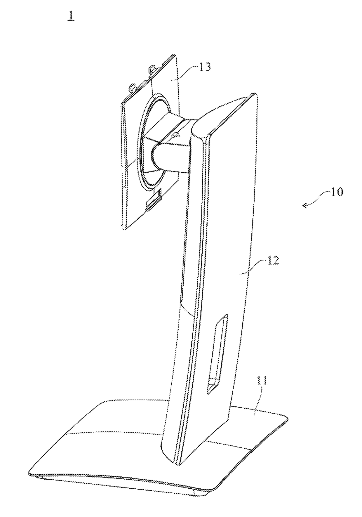
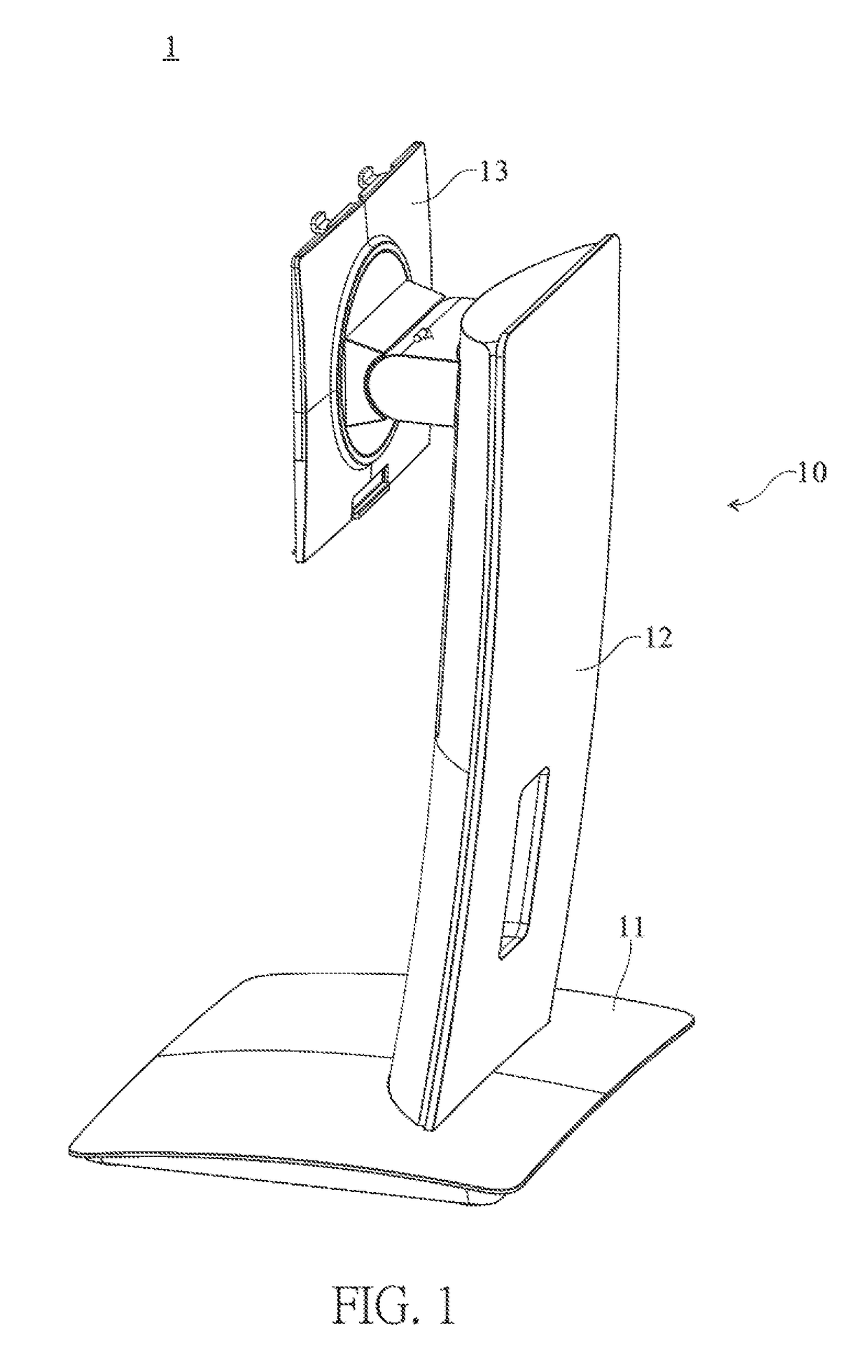
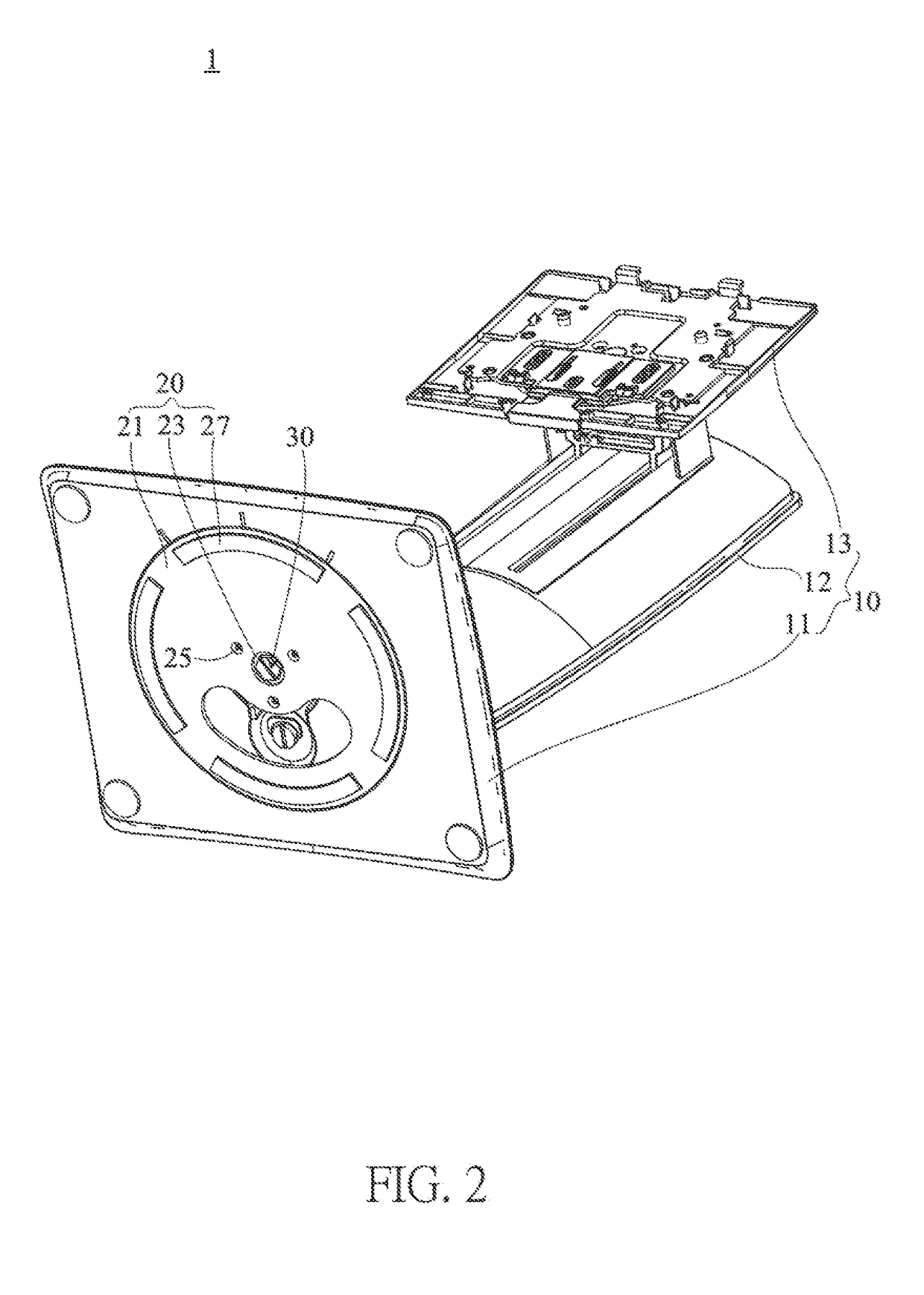
[0023]Please refer to FIGS. 1 and 2, which are perspective schematic views of a swivel supporting device 1 at different angular orientations in accordance with the present invention. The swivel supporting device 1 of the present invention mainly comprises a stand 10, a baseplate 20 and a switchable structure 30. The stand 10 includes a base 11, an upright 12 extending from the base 11, and a fixing plate 13 associated with the upright 12 for holding a display device (not shown in the figures). For clear illustration of the baseplate 20 and the switchable structure 30 of the swivel supporting device 1 hid by the base 11 in FIG. 1, FIG. 2 is further provided to show the swivel supporting device 1 at another angular orientation. Additionally, in this embodiment, the base 11 is formed by die casting, but not limited thereto.

[0024]In this illustration, the switchable structure 30 is disposed on the stand 10, and thus can be brought into rotation with respect to the baseplate 20 through t...


PUM


Abstract

A swivel supporting device comprising a stand, a baseplate and a switchable structure connecting with the stand and the baseplate is provided. The switchable structure includes a plurality of washers being axially associated with each other. An external force for driving the stand and the switchable structure rotating with respect to the baseplate is capable of being adjusted depending on the extent of the engagement interference between the washers.

Description

CROSS REFERENCE TO RELATED APPLICATION[0001]This application claims the benefits of the Taiwan Patent Application Serial Number 104212640, filed on Aug. 6, 2015, the subject matter of which is incorporated herein by reference.BACKGROUND OF THE INVENTION[0002]1. Field of the Invention[0003]The present invention relates to a supporting device, and more particularly to a swivel supporting device used for holding a display device and provided with function of pivotal-resistance adjustment.[0004]2. Description of Related Art[0005]Disclosed in U.S. Pat. No. 7,748,680 is a stand that includes a swivel for pivot motion in right and left directions at a predetermined angle. The swivel itself can be pivotally rotated and has multiple bolts each inserted into an arc-shaped guide trough such that the pivot angle of a display device can be adjusted within the range of the guide trough by the swivel.[0006]Although the display device mounted on the disclosed stand can be pivotally rotated, the wei...

Claims


Application Information

Patent Timeline
Patent Type & Authority Patents(United States)
IPC IPC(8): F16M13/00F16M11/12F16M11/20
CPCF16M11/2014F16M11/126F16M2200/08F16M11/10F16M11/24F16M2200/022
Inventor YEH, CHING-YIWANG, JUEI-HSIEN
Owner SYNCMOLD ENTERPRISE CORP
Why Eureka
Try Eureka