Eureka AIR delivers breakthrough ideas for toughest innovation challenges, trusted by R&D personnel around the world.

Uniaxial eccentric screw pump

a screw pump and eccentric screw technology, applied in the direction of pump components, machines/engines, liquid fuel engines, etc., can solve the problems of rotor damage, rotor cannot be rotated, rotor wear on the stator body, etc., and achieve the effect of smooth conveying

Active Publication Date: 2016-11-24
HEISHIN ENGINEERING & EQUIPMENT CO LTD
View PDF4 Cites 2 Cited by
  • Summary
  • Abstract
  • Description
  • Claims
  • Application Information

AI Technical Summary

Benefits of technology

The patent describes a pump that prevents the stator from getting in contact with the rotor when a high temperature fluid flows through it. This is done by making the stator expand in the outer diameter direction, which prevents the stator from coming into pressure contact with the rotor. This helps to prevent wear and tear on the stator without the need for adjusting interference between the stator and rotor. The technical effect of this invention is to improve the reliability and efficiency of the pump without requiring a cumbersome adjusting operation.

Problems solved by technology

When the rotor is rotated in such a state, a frictional force of the rotor against the stator body becomes excessively large and hence, there may be a case where an abnormal wear occurs on the stator body or the rotor is damaged.
Further, there may be also a possibility that the rotor cannot be rotated.
However, such an interference adjusting operation is a complicated and cumbersome operation which must be performed manually.

Method used


Image

  • Uniaxial eccentric screw pump
  • Uniaxial eccentric screw pump
  • Uniaxial eccentric screw pump

Examples


Embodiment Construction

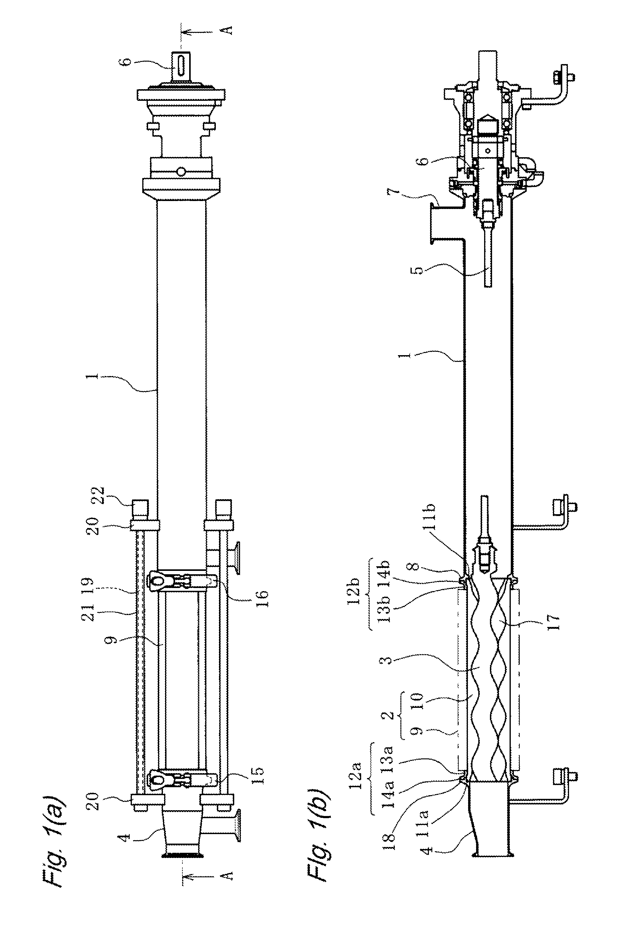
[0047]Hereinafter, embodiments according to the present disclosure are described with reference to attached drawings. In the description made hereinafter, terms indicating specific directions and positions (terms including “upper”, “lower”, “side”, and “end”, for example) are used when necessary. However, these terms are used for facilitating the understanding of the disclosure described with reference to the drawings, and the technical scope of the present disclosure is not limited by the meaning of these terms. Further, the description made hereinafter essentially only exemplifies examples of the present disclosure, and the description is not intended to limit the present disclosure, a product to which the present disclosure is applied, or the application of the present disclosure. Further, drawings are schematically shown, and the size ratios of respective parts and the like differ from those of actual parts.

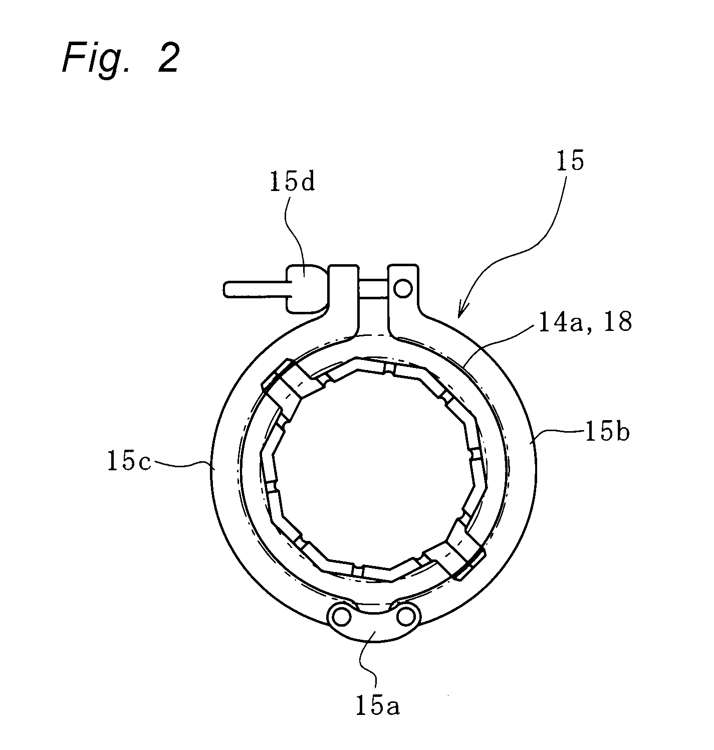
[0048]FIG. 1 shows a uniaxial eccentric screw pump according to this emb...


PUM


Abstract

A uniaxial eccentric screw pump includes: a casing 1; a stator 2 having one end portion thereof connected to the casing 1 and having an inner peripheral surface which is formed into a female threaded shape; a rotor 3 configured to be insertable into the stator 2 and formed of a shaft body having a male threaded shape; and an end stud 4 connected to the other end portion of the stator 2. The stator 2 is configured to be expandable and shrinkable in a radial direction.

Description

CROSS-REFERENCE TO RELATED APPLICATIONS[0001]This is a National Stage application of International Patent Application No. PCT / JP2014 / 082142, filed on Dec. 4, 2014, which claims priority to Japanese Patent Application No. 2014-013541 filed on Jan. 28, 2014, the disclosures of which are incorporated herein by reference in their entireties.TECHNICAL FIELD[0002]The present disclosure relates to a uniaxial eccentric screw pump.BACKGROUND ART[0003]Conventionally, as a uniaxial eccentric screw pump, there has been known a uniaxial eccentric screw pump having the configuration where a stator is formed of a stator body and an outer sleeve, and the outer sleeve can be easily split from the stator body (see Japanese Unexamined Patent Application Publication No. 2012-137038, for example).[0004]In such a conventional uniaxial eccentric screw pump, there may be a case where an internal surface of the stator body is cleaned and sterilized simultaneously with the supply of a high-temperature fluid ...

Claims


Application Information

Patent Timeline
IPC IPC(8): F04C2/107F04C15/00
CPCF04C2/1075F04C15/0015F04C2240/30F04C2240/20F04C2210/44F04C2240/10F04C2/107
Inventor TANAKA, KEI
Owner HEISHIN ENGINEERING & EQUIPMENT CO LTD
Why Eureka
Eureka Blog
Learn More