
Structure of mounting rear fork in vehicle such as motorcycle

a rear fork and motorcycle technology, applied in the direction of foldable cycles, cycle equipment, cycles, etc., can solve the problems that the driving information of the rear wheel is difficult to be smoothly conveyed to the driver, and achieve the effect of accurate conveying driving information and excellent riding comfor

Active Publication Date: 2005-07-05
HONDA MOTOR CO LTD
View PDF5 Cites 13 Cited by
  • Summary
  • Abstract
  • Description
  • Claims
  • Application Information

AI Technical Summary

Benefits of technology

[0006]The present invention has been achieved in view of the above-described state of affairs, and is aimed to provide a structure for mounting a rear fork in a vehicle such as a motorcycle, capable of accurately conveying driving information of the rear wheel to the driver when the rotation characteristic of the rear fork draws a smooth straight line or curved line. Thus, the driver can have excellent riding comfort.
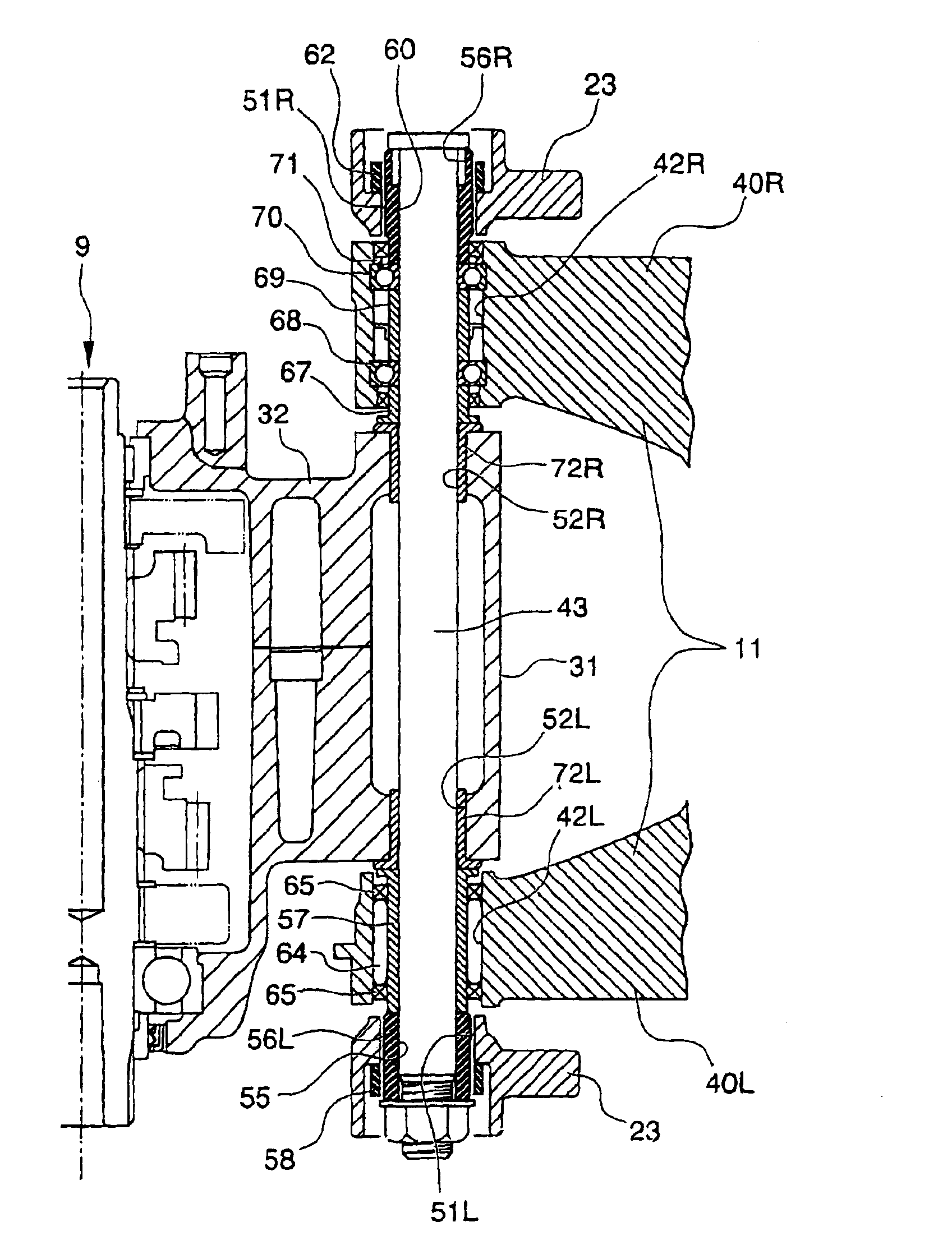
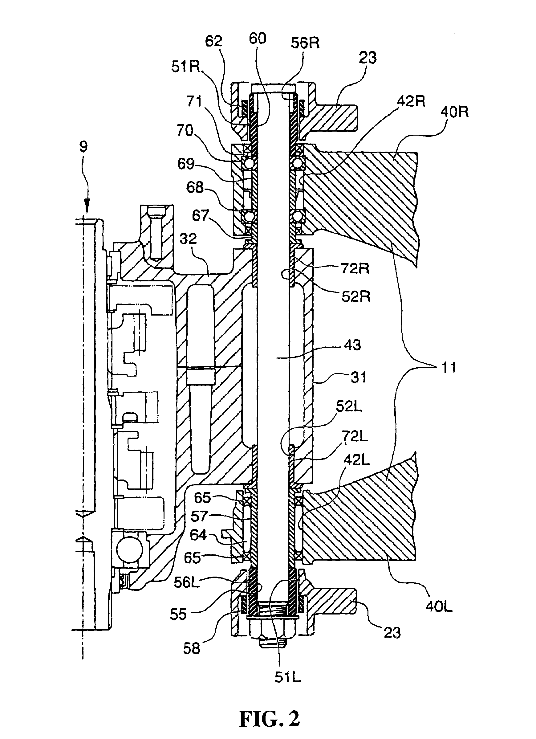
[0014]According to the present invention, a load such as a road reaction force or a driving force is applied to the pivot shaft through the rear fork from the rear wheel and the pivot shaft is going to deflect. At that time, however, since there is provided a cutout on an end surface portion of the pivot supporting hole of the body frame or the pivot supporting hole of the engine, the pivot shaft freely deflects only by the amount corresponding to this cutout being provided. Also, at this time, the pivot shaft comes into contact with the neighborhood of the end surface portion of those pivot supporting holes at a broader area than when it comes into line-contact with the end surface of the pivot supporting hole of the conventional vehicle frame or engine. For this reason, no strong shearing force is locally exerted on the pivot shaft, but a rotation characteristic of the rear fork is to draw a smooth straight line or curved line and as a result, driving information of the rear wheel is smoothly conveyed to the driver.

Problems solved by technology

Also, at this time, a strong shearing force is locally exerted on the pivot shaft As a result, the rotational characteristic of the rear fork does not draw any smooth curved line, resulting in a phenomenon in which driving information of the rear wheel becomes difficult to be smoothly conveyed to the driver.

Method used


Image

  • Structure of mounting rear fork in vehicle such as motorcycle
  • Structure of mounting rear fork in vehicle such as motorcycle
  • Structure of mounting rear fork in vehicle such as motorcycle

Examples


Embodiment Construction

[0022]Hereinafter, with reference to the drawings, the description will be made of embodiments for a motorcycle equipped with a structure for mounting a rear fork according to the present invention. In this respect, in the description, the directions such as “before and behind” and “left and right” shall be defined with the vehicle body as the reference.

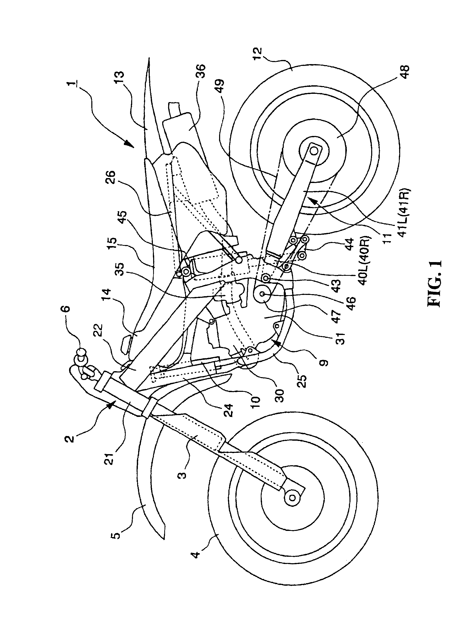
[0023]FIG. 1 is a side view showing the general construction of a motorcycle equipped with a structure for mounting a rear fork according to the present invention.

[0024]The motorcycle 1 is for so-called off-road operation, and includes a body frame 2, a pair of left and right telescopic type front forks 3 pivotally supported by a front end of the body frame 2, a front wheel 4 rotatively supported by a lower end of the front fork 3, a front fender 5 supported by the front fork 3 for covering the upper part of the front wheel 4 and a steering wheel 6 mounted to an upper end of the front fork 3 and arranged above at the front portion of...


PUM


Abstract

A structure for mounting a rear fork in a vehicle, including a body frame having left and right pivot supporting holes; left and right arm portions of a rear fork having supporting holes which are coaxial with the right and the left pivot supporting holes of the body frame a pivot shaft penetrating the pivot supporting holes of said body frame and the supporting holes of the left and right arm portions of the rear fork, said rear fork being rotatively supported on the pivot shaft and being rotatable with respect to said body frame. A tapered cutout is provided on the end surface portion of the collar to be pressed into the pivot supporting hole of the engine, so as to allow the pivot shaft to deflect.

Description

CROSS-REFERENCE TO RELATED APPLICATIONS[0001]The present application claims priority under 35 USC 119 to Japanese Patent Application Nos. 2002-288022 filed on Sep. 30, 2002 the entire contents thereof are hereby incorporated by reference.FIELD OF THE INVENTION[0002]The present invention relates to structure of mounting a rear fork in a vehicle such as a motorcycle.DESCRIPTION OF BACKGROUND ART[0003]Conventionally, a structure for mounting a rear fork on a vehicle such as a motorcycle is known as disclosed for example, in Japanese Patent Laid-Open No. 2000-85673 in which between left and right pivot supporting holes of a body frame, pivot supporting holes of an engine supported by the body frame are arranged so as to become coaxial. In addition, between the pivot supporting holes of the body frame and pivot supporting holes of the engine, there are arranged supporting holes capable of being rotated with respect to left and right arm portions of the rear forks, respectively, so as to ...

Claims


Application Information

Patent Timeline
IPC IPC(8): B62K25/00B62K25/26B62K25/20
CPCB62K25/00
Inventor UNETA, HISASHIHONDA, TAICHI
Owner HONDA MOTOR CO LTD
Learn More