Work conveying method and conveying apparatus employing the conveying method

Inactive Publication Date: 2008-07-03
HIROTEC CORP
View PDF7 Cites 12 Cited by
  • Summary
  • Abstract
  • Description
  • Claims
  • Application Information

AI Technical Summary

Benefits of technology

[0006]The present invention has been made in view of the foregoing and has its object of increasing the production efficiency by automating a task of taking out works and conveying them up to a target site and by devising a work conveying procedure in the automated task.
[0009]In short, the conveyance robot automatically conveys the works to the target site with the operator's labor eliminated. Further, a plurality of works are taken out at one time from the work storing means, which eliminates the need to perform the step of moving the work gripping means to the work storing means for taking out a work every time conveyance of one work is completed, reducing time required for conveying the works as a whole. The work storing means stores a plurality of works in the form of sets to increase the space efficiency, resulting in that the number of works that the work storing means can store increases. This lowers the frequency of carrying in and out the work storing means. Thus, the production efficiency increases.
[0012]As a result, this invention reduces time required for work conveyance by automating the work conveyance and needs less or no positional correction of the work after conveyance by conveying the work to the target site accurately, thereby increasing the production efficiency.
[0014]In the above arrangement, similarly to the first invention, work conveyance is automated, and it becomes unnecessary to move the work gripping means to the work storing means for taking out works every time conveyance of one work is completed, thereby reducing time required for work conveyance as a whole. In addition, the number of works that single work storing means can store increases to lower the frequency of carrying in and out the work storing means. Thus, the production efficiency increases.
[0015]Furthermore, every work can be conveyed to the target site accurately to eliminate the need for positional correction of the work after conveyance. This also increases the production efficiency.
[0017]With the above arrangement, the other work can be held to the temporal work holding means without taking off the work to be conveyed first to the target site from the suction cup of the work gripping means, thereby further reducing time required for work conveyance. Further, deformation and damage of the works in sucking the works to the suction cup can be suppressed.

Problems solved by technology

This restricts reduction in time required for conveying the works from the work storing means to the target site, involving difficulty in increasing the production efficiency.

Method used


Image

  • Work conveying method and conveying apparatus employing the conveying method
  • Work conveying method and conveying apparatus employing the conveying method
  • Work conveying method and conveying apparatus employing the conveying method

Examples


Embodiment Construction

[0036]Hereinafter, one embodiment of the present invention will be described in detail with reference the accompanying drawings. It should be noted that the following preferable embodiment substantially describes a mere example and is not intended to limit the present invention, applicable objects thereof, and use thereof.

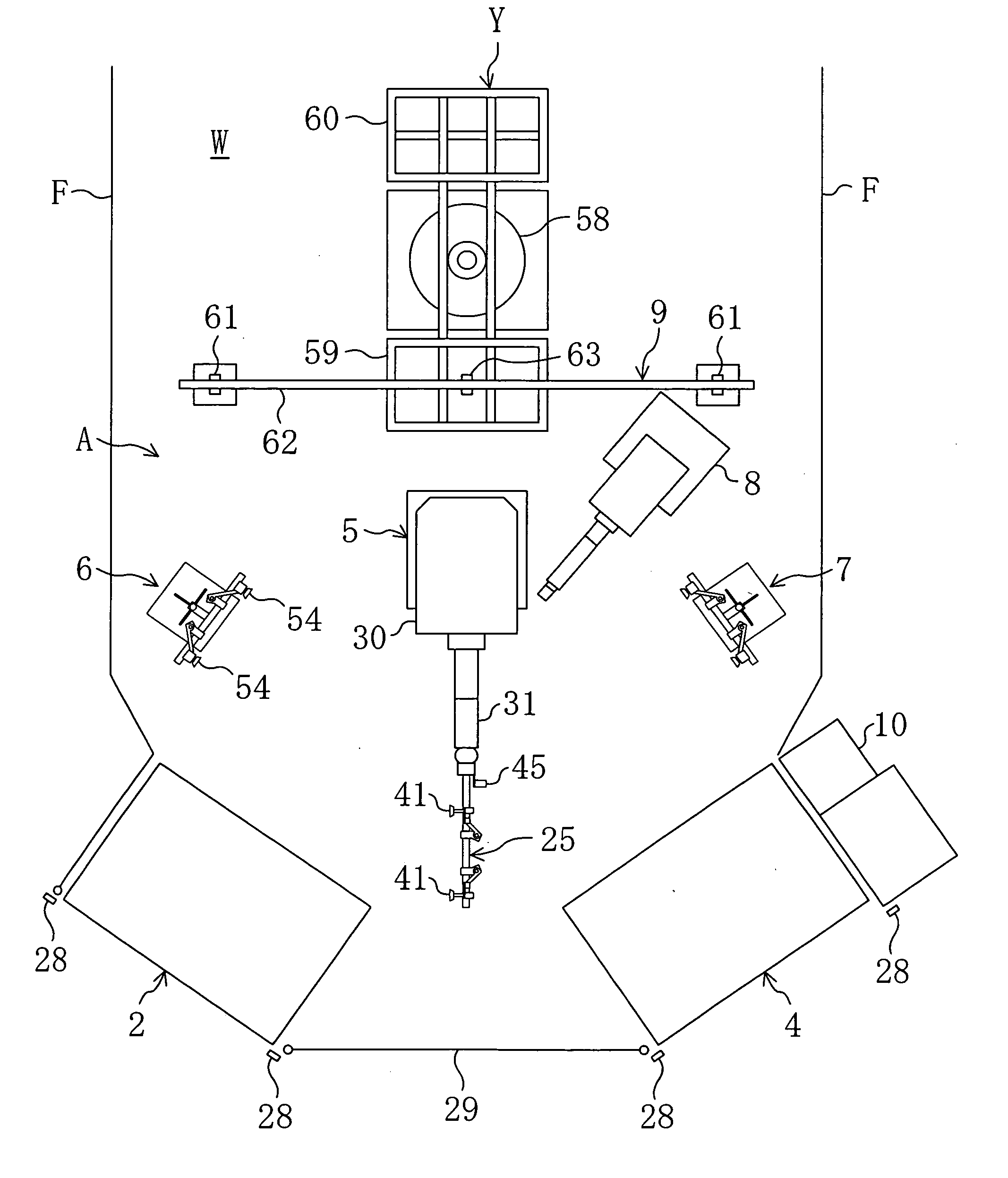
[0037]FIG. 1 shows a work conveying apparatus A according to the embodiment of the present invention. The conveying apparatus A is installed in a factory W for assembling doors (not shown) to be provided at the respective sides of an automobile. The conveying apparatus A conveys outer panels P (work) of a door to a fixed point of a jig Y for a step thereafter.

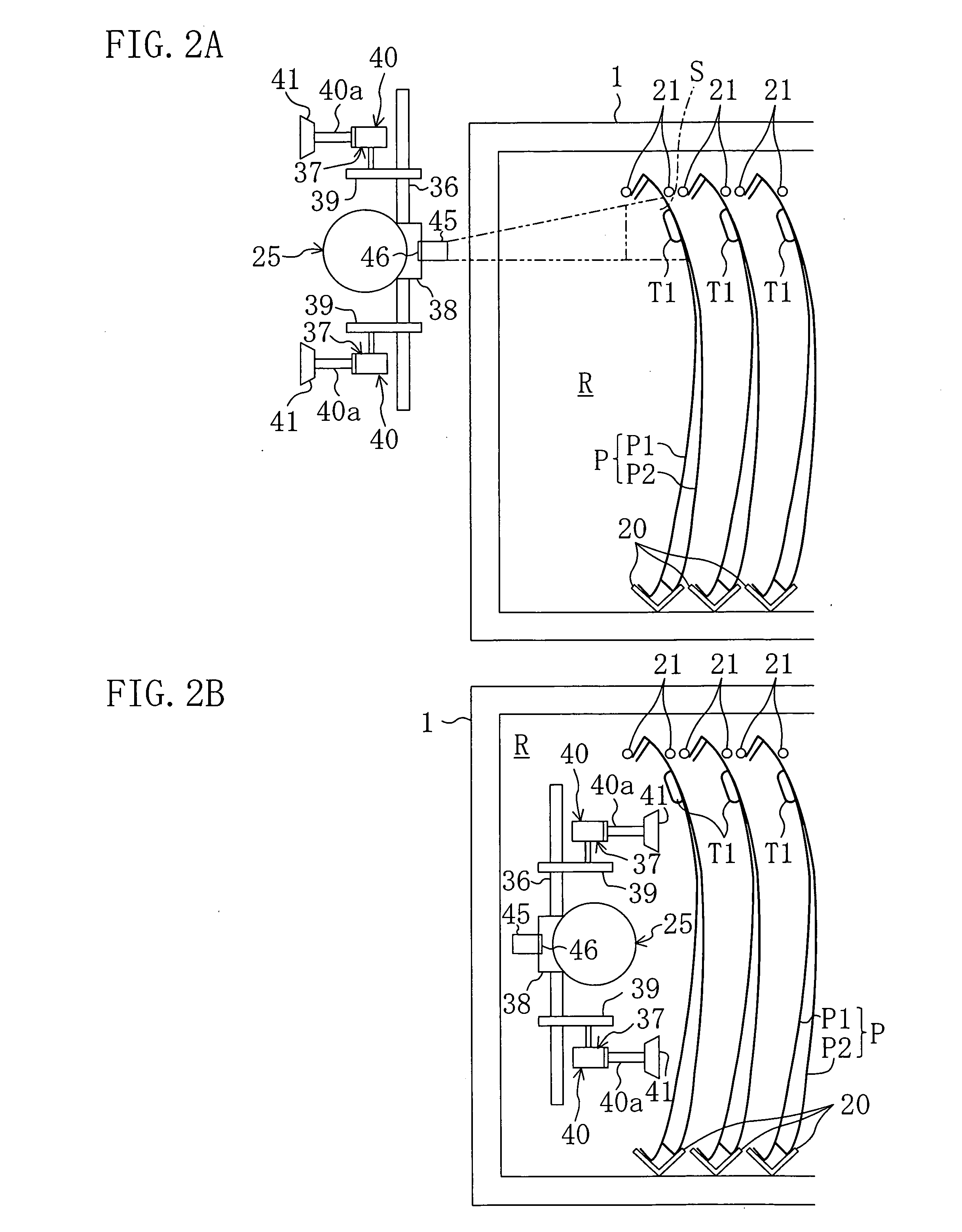
[0038]Before describing the construction of the conveying apparatus A, the outer panels P will be described first. The outer panels P are formed by press-forming steel plates and each have an intermediate part in the vertical direction which is curved outboard greatly when mounted to an automobile, as shown in...


PUM


Abstract

Plural wok pairs composed of a plurality of works are stored in work storing means. A movable sensor 45 fitted to a conveyance robot 5 detects the position of one of the work pairs in the work storing means, and the work gripping means 25 takes out a plurality of works at one time from the work storing means. One of the plurality of works is held temporally by temporal work holding means 6 or 7 while the other work is conveyed to a jig Y. In the course of conveyance, a fixed sensor 63 detects the relative positional relationship between the work and the work gripping means 25. If the relative positional relationship deviates from the regular positional relationship, the movement of a robot arm 31 is corrected.

Description

BACKGROUND OF THE INVENTION [0001]1. Field of the Invention[0002]The present invention relates to a work conveying method and a conveying apparatus employing the conveying method.[0003]2. Background Art[0004]Conventionally, a door provided in an automobile, for example, is formed by joining an outer panel and an inner panel. A door having such a structure is manufactured in such a manner that: an outer panel and an inner panel (works) are formed by a press forming machine and then are stored once in work storing means, such as a pallet; the work storing means is conveyed to a site where a door assembling machine is placed; one of a plurality of works stored in the work storing means is taken out, is conveyed to an assembling jig, and is positioned at and held to the jig; and then, the work held to the jig is subjected to various kinds of assembling processes (see, Japanese Patent Application Laid Open Publication No. 11-321735A, for example).[0005]In order to take out works stored i...

Claims


Application Information

Patent Timeline
IPC IPC(8): B25J3/00
CPCB25J15/0052B25J15/0061B62D65/18
Inventor TOMINAGA, MAKOTO
Owner HIROTEC CORP
Why Eureka
Try Eureka