Spring-loaded pressure relief valve, particularly for containers of pressurized fluids

a pressure relief valve and spring-loaded technology, which is applied in the direction of functional valve types, water supply installation, pipe elements, etc., can solve the problems of over-replacing of devices, increasing the cost of replacement, and reducing the safety value of devices

Active Publication Date: 2006-07-18
CAVAGNA GROUP
View PDF15 Cites 12 Cited by
  • Summary
  • Abstract
  • Description
  • Claims
  • Application Information

AI Technical Summary

Benefits of technology

[0013]The aim of the invention is to overcome the drawbacks noted above, by providing a spring-loaded pressure relief valve, particularly for containers of pressurized fluids, that allows to optimize the outflow of pressurized fluids, with the possibility to convey them correctly outward without causing problems for the surrounding environment.

Problems solved by technology

The direct action of the spring on the piston, however, causes intense stress on the gasket of the sealing device, which, by being generally made of plastics acquires over time a deformation that corresponds to the shape of the valve port, consequently altering the initial set value.
In some cases, the difference between the initial set pressure and the actual intervention pressure, after a period of time that is not easy to quantify, exceeds the intended safety value and the device must be replaced.
Clearly, this situation forces to proceed to periodic inspections, with considerable financial burdens that can be further increased by the need to perform frequent valve replacements.
This type of valve suffers several drawbacks, the first of which is constituted by the fact that the pressurized fluid is discharged in a radial direction with respect to the valve body, accordingly causing considerable problems in applications on tanks that contain flammable gases or liquids.
Furthermore, another problem is constituted by the fact that when it is necessary to replace the auxiliary valve, the intervention performed inevitably removes the setting of said valve and therefore in most cases it is necessary to disassemble the valve completely and to replace and consequently set the auxiliary valve directly at the factory, with the obvious associated problems.

Method used


Image

  • Spring-loaded pressure relief valve, particularly for containers of pressurized fluids
  • Spring-loaded pressure relief valve, particularly for containers of pressurized fluids
  • Spring-loaded pressure relief valve, particularly for containers of pressurized fluids

Examples


Embodiment Construction

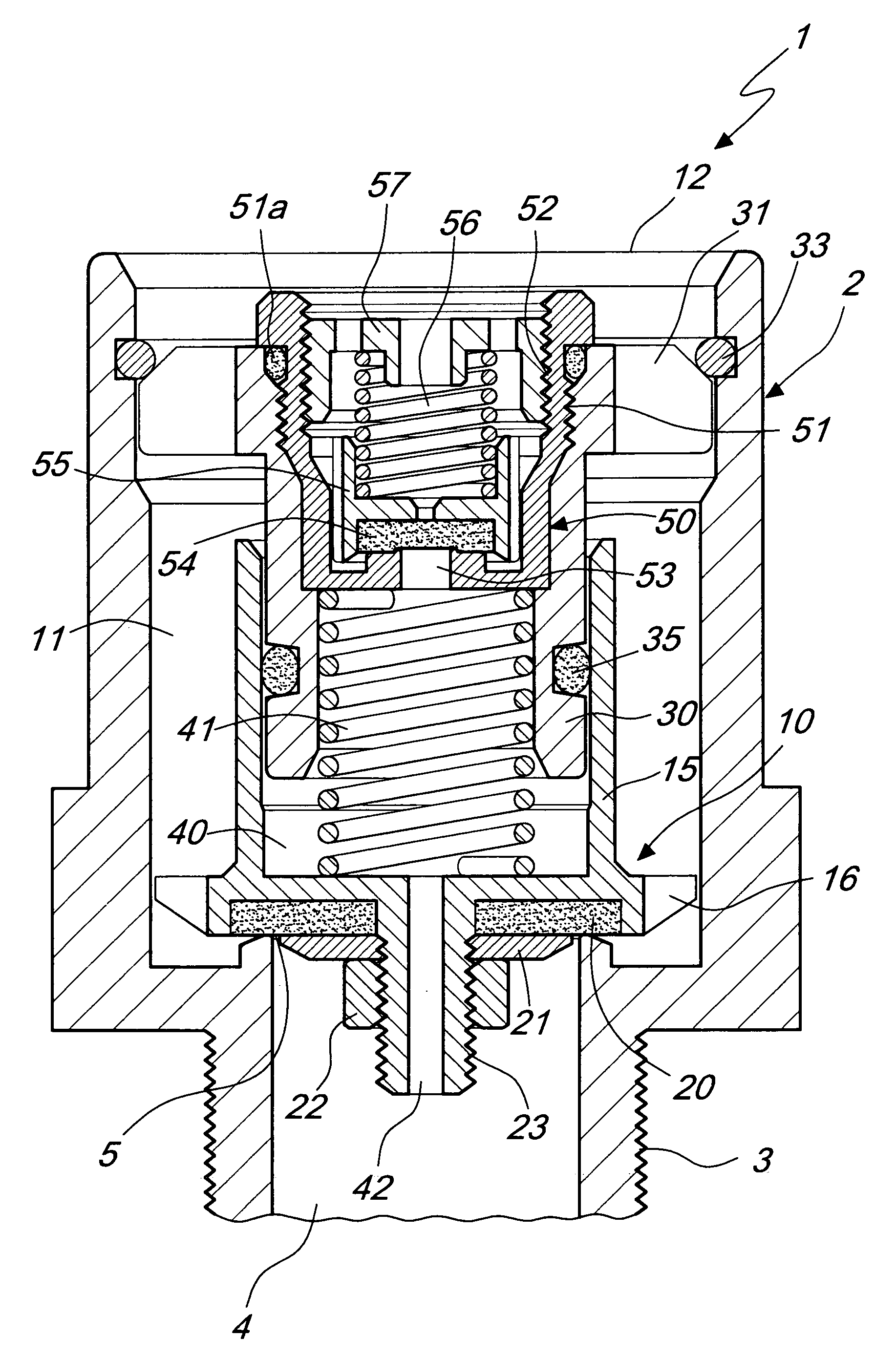
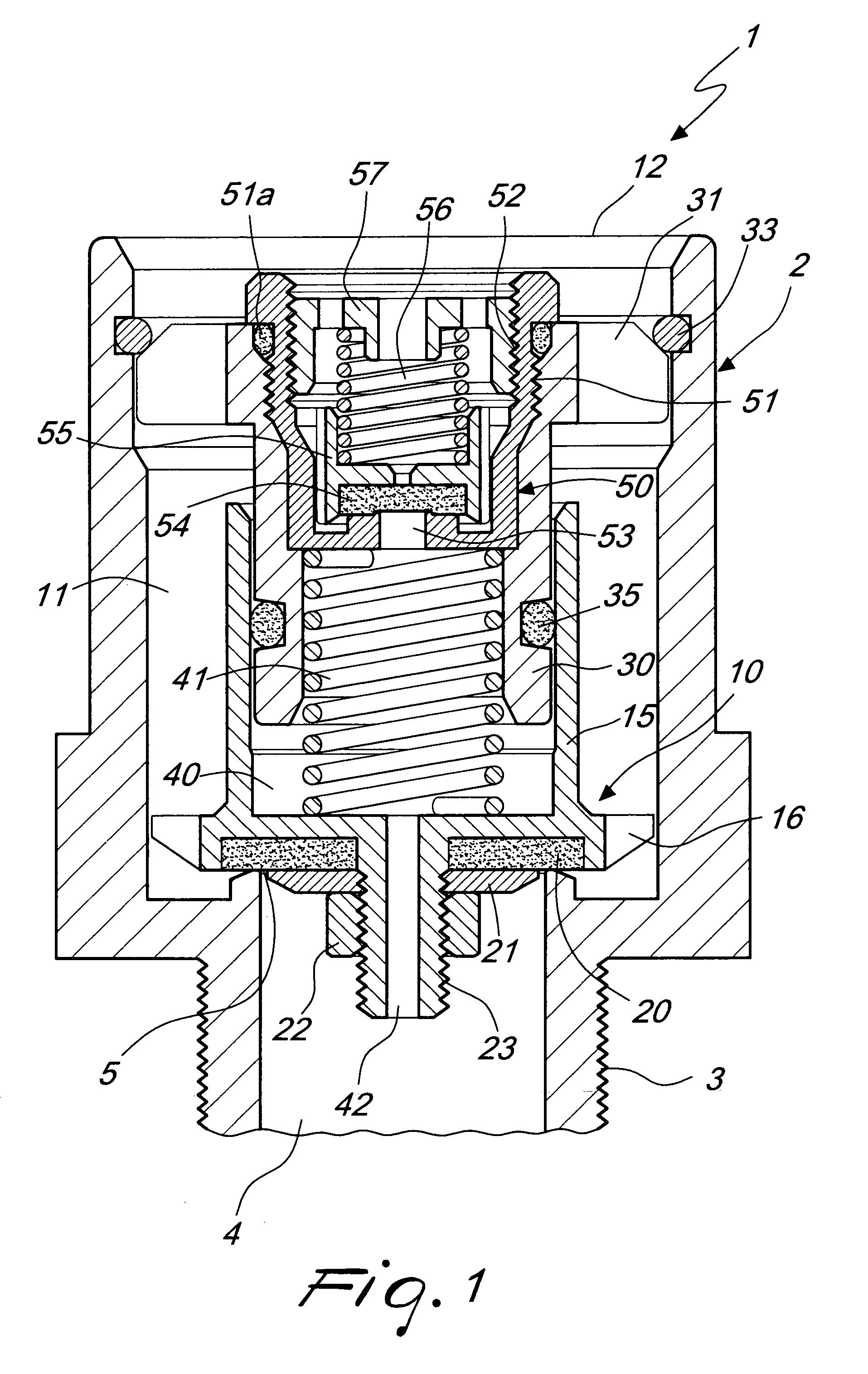
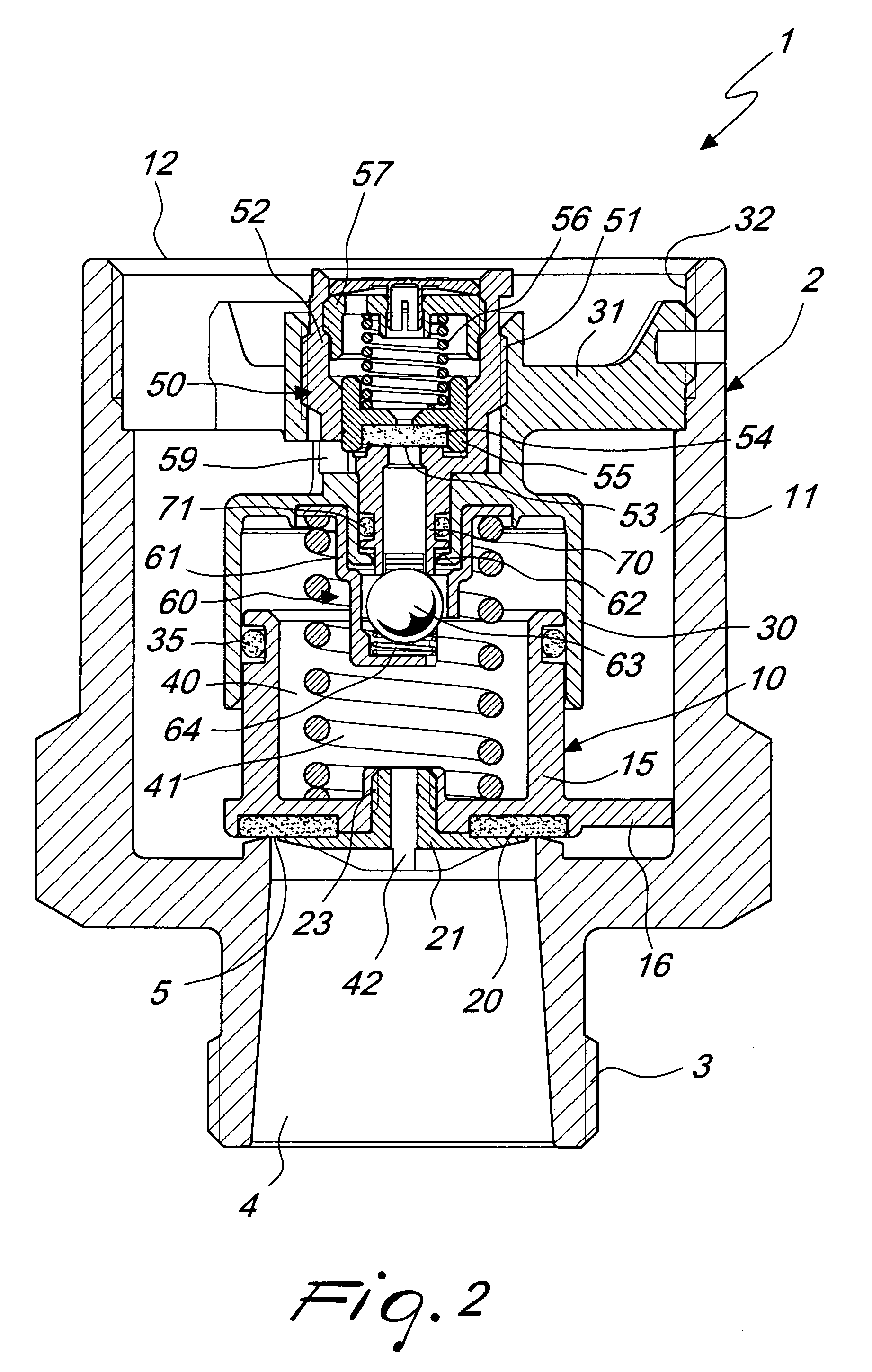
[0024]With reference to the figures, the spring-loaded pressure relief valve, particularly for containers of pressurized fluids, according to the invention, generally designated by the reference numeral 1, comprises a valve body 2 that is provided with a threaded connector 3 for its connection to a container of pressurized fluid in general.

[0025]The connector 3 delimits a passage 4, which forms a discharge port 5 controlled by a main piston, generally designated by the reference numeral 10.

[0026]The piston 10 is accommodated in a preferably cylindrical cavity 11, which is formed in the valve body 2 and has, on the opposite side with respect to the discharge port 5, an open end, designated by the reference numeral 12, that forms in practice an outlet in an axial direction.

[0027]As shown in FIGS. 1 to 4, the piston 10 has a cylindrical piston body 15 which has, at its base, radial wings 16 that act as a guide for the sliding of the piston in the cavity 11, allowing to discharge the fl...


PUM


Abstract

A spring-loaded pressure relief valve, particularly for containers of pressurized fluids, comprising a valve body that is associable with a container and forms a discharge port that is controlled by a main piston; an auxiliary valve is further provided, which controls a venting port and drives the intervention of the main piston, such main piston being accommodated in a cavity that is formed in the valve body and is open in an axial direction on the opposite side with respect to the venting port.

Description

BACKGROUND OF THE INVENTION[0001]The present invention relates to a spring-loaded pressure relief valve, particularly for containers of pressurized fluids.[0002]As is known, spring-loaded pressure relief valves are usually fitted on containers intended to contain pressurized fluids; such valves are designed to prevent the pressure from increasing beyond the limits for which the container has been manufactured.[0003]The operating principle of these valves is based on the possibility to automatically discharge, without further intervention except for the intervention produced by the pressure of the involved fluid, a certified amount of fluid, so as to prevent the preset safety pressure from being exceeded, furthermore, interrupting such discharge when normal operating pressure conditions are reestablished.[0004]Currently known spring-loaded pressure relief valves generally have a system for adjusting the opening pressure of the valve that is based on the compression of a spring, which...

Claims


Application Information

Patent Timeline
Patent Type & Authority Patents(United States)
IPC IPC(8): F16K17/10F16K43/00
CPCF16K17/10Y10T137/7838Y10T137/7766Y10T137/6191Y10T137/6195Y10T137/88054
Inventor CAVAGNA, CARLO
Owner CAVAGNA GROUP
Why Eureka
Try Eureka