
Water purifier filtration portion, water purifier main body, and water purifier including the both

a technology of water purifier and filtration portion, which is applied in the direction of filtration separation, separation process, coupling, etc., can solve the problems of filtration portion falling off, time-consuming attachment job, unexpectedly demanding time-consuming operations, etc., and achieves the effect of reducing a number of components, facilitating the fall off and saving spa

Inactive Publication Date: 2005-04-19
OSAKA GAS CHEM KK
View PDF11 Cites 13 Cited by
  • Summary
  • Abstract
  • Description
  • Claims
  • Application Information

AI Technical Summary

Benefits of technology

[0026]It is therefore an object of the present invention to provide a water purifier equipped with a connection mechanism, with which a user can connect a cartridge to a water purifier main body in a single step with ease in a secure manner, and a filtration portion will not easily fall off even when water with a high water pressure flows in. It is another object of the present invention to provide a water purifier filtration portion capable of notifying the user of the service life of the filtration material accurately, ensuring a fluid-tight condition between an indicator portion and a cartridge portion, reducing a number of components, and saving a space in the vicinity of the faucet, and a water purifier including the same.
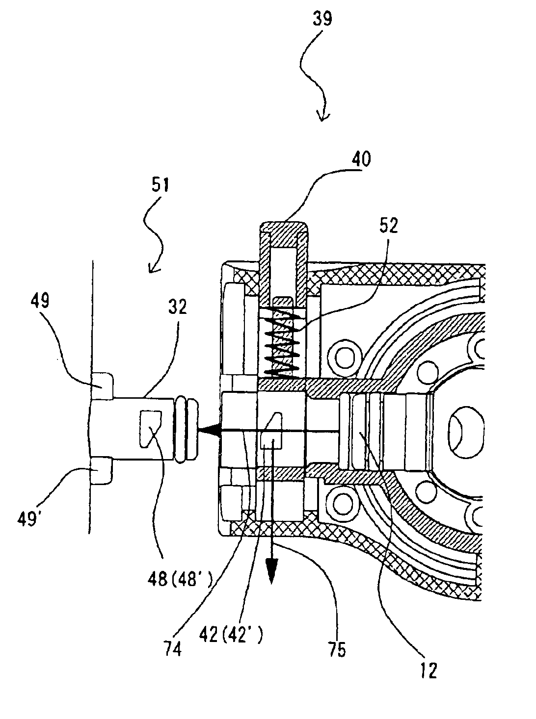
[0030]According to the above arrangements, the main body side coupling portion is provided with the main body side stopping member for coupling the water purifier filtration portion to the water purifier main body by stopping and being stopped by the filtration portion side stopping member provided to the water purifier filtration portion. Hence, it is possible to connect the water purifier filtration portion to the water purifier main body in a single step with ease in a secure manner. Also, the main body side stopping member is provided in such a manner that the main body side stopping member is allowed to move only in one direction that is substantially perpendicular to a flowing direction of water passing by the main body side coupling portion in the connection operation and the disconnection operation. Hence, even when a load is applied to the main body side stopping member or the filtration portion side stopping member by a sporadic change in water pressure, the connection will not be disconnected unless a partial pressure that causes the main body side stopping member to move in the above-specified one direction is applied, which prevents the main body side stopping member from being detached easily. Consequently, it is possible to provide a water purifier main body equipped with a connection mechanism, with which the filtration portion will not fall off easily even when water with a high water pressure flows in.
[0032]According to the above arrangement, the pressure sensing portion provided to the drum is formed from the resilient body provided on the wall surface of the drum and the protrusion portion protruding toward the display portion from the resilient body. Hence, while a fluid flown in from the raw water accepting inlet flows through the channel, the pressure sensing portion expands and extends due to its resilience in response to an internal pressure in the channel. Also, the protrusion portion is formed to protrude from the resilient body. Hence, by converting the expansion and extension of the resilient body into a slight movement toward the display portion, it is possible to convey such expansion and extension accurately. Also, the first conductive member is separated from the drum and the electric circuit. Hence, the drum, which is to be replaced, can be of a simpler structure, so that not only can a total number of components be reduced, but also a space can be saved. Also, the first conductive member is provided at a position where it is brought into contact with the first input portion by a water pressure conveyed from the pressure sensing portion to close the electric circuit. Hence, it is possible to notify the service life of the filtration material accurately by accumulating time while water pressure is sensed.

Problems solved by technology

According to the conventional water purifier discussed above, however, the operation to engage the filtration portion 62 with the water purifier main body 61 involves the first and second steps with no exception, which poses a problem that the attachment job is time-consuming.
Hence, the conventional water purifier has a problem that it unexpectedly demands time-consuming operations.
Hence, the conventional water purifier has a problem that there is a likelihood that the filtration portion falls off when a stream of water with a high water pressure flows in sporadically.
However, in order to accumulate a total volume of water by the mechanical method using the mechanisms described in the above-cited publication, it is necessary to provide a rotary mechanism composed of a combination of a turbine, a plurality of gears, etc. inside the cartridge, which undesirably increases the cartridge itself in size, thereby posing a problem that it becomes difficult to save a space.
This poses a problem that there is a high risk that the user may erroneously wet the electric circuit board when he replaces the cartridge.
Hence, there is a problem that materials of the flexible cap are limited to those having flexibility at or above a certain level.
This makes it difficult to save a space, and increases the number of components, and hence the manufacturing costs.

Method used


Image

  • Water purifier filtration portion, water purifier main body, and water purifier including the both
  • Water purifier filtration portion, water purifier main body, and water purifier including the both
  • Water purifier filtration portion, water purifier main body, and water purifier including the both

Examples


Embodiment Construction

[0065]The following description will describe one embodiment of the present invention with reference to the accompanying drawings.

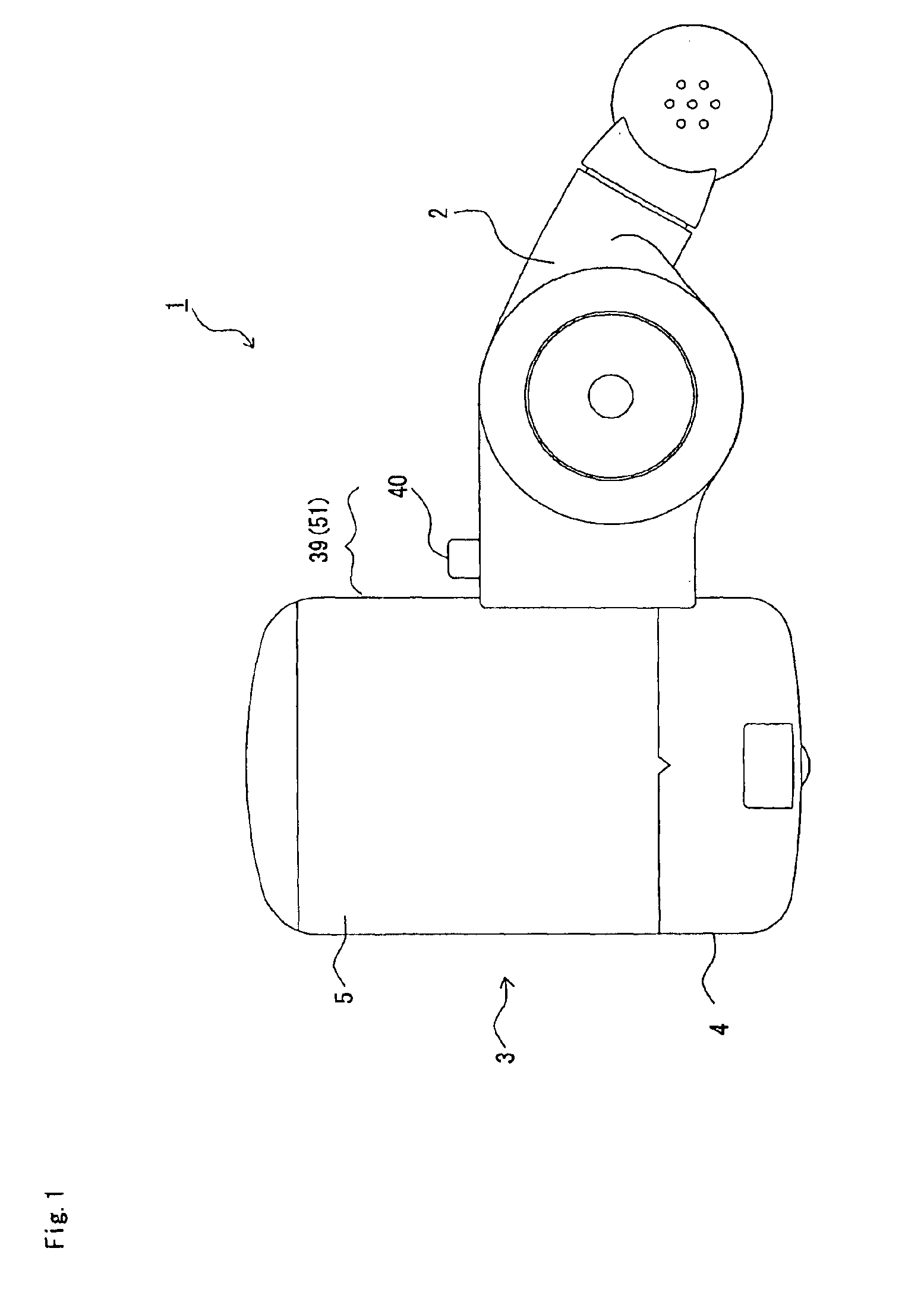
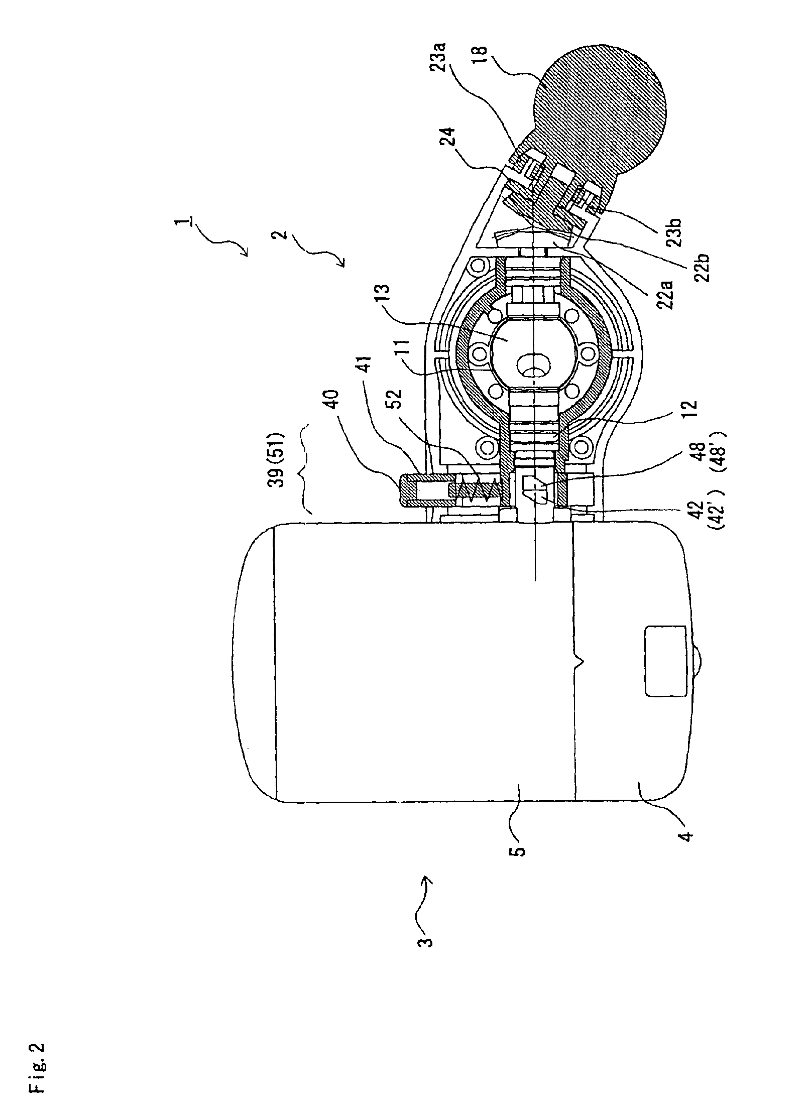
[0066]FIG. 1 is a plan view schematically showing an arrangement of a water purifier according to the present embodiment. FIG. 2 is an explanatory view replacing the plan view in FIG. 1 with a cross section for a valve main body 2 alone. FIG. 3 is a front view schematically showing the arrangement of the water purifier according to the present embodiment. FIG. 4 is an explanatory view replacing the front view in FIG. 3 with a longitudinal section for the valve main body 2 alone.

[0067]As is shown in FIG. 1, a water purifier 1 according to the present embodiment is composed of the valve main body 2 (a water purifier main body) coupled to an unillustrated tap water faucet, and a filtration portion 3 (water purifier filtration portion), connected to the valve main body 2 in a detachable and attachable manner, for holding a filtration material that filters raw...


PUM

PropertyMeasurementUnit
Angleaaaaaaaaaa

Abstract

A water purifier is composed of a valve main body and a filtration portion, which are coupled to each other in an attachable and detachable manner at the main body side coupling portion and the filtration portion side coupling portion. Consequently, the water purifier filtration portion can be connected to the water purifier main body in a single step with ease in a secure manner, and at the same time, the water purifier filtration portion will not fall off easily even when water with a high water pressure flows in. Also, the water purifier is provided with a concave portion and a sensor packing formed as an integral portion of the concave portion and protruding toward an indicator portion on a wall surface of a cartridge. The indicator portion is provided with a conductive member at a position where it is brought into contact with a first input portion by a water pressure and thereby closes an electric circuit on a circuit board. Consequently, the service life (the rated service cycle) of a filter material (medium) can be notified to the user accurately, and a fluid-tight condition of the indicator portion and the cartridge portion can be ensured.

Description

FIELD OF THE INVENTION[0001]The present invention relates to a water purifier filtration portion, a water purifier main body, and a water purifier including these components employed in or as a water purifier for home or commercial use. More specifically, the present invention relates to a water purifier filtration portion that is easy to attach to and detach from a water purifier main body and is also easy to replace, a water purifier main body, and a water purifier including these components. The present invention also relates to a water purifier filtration portion equipped with a display (indicator) portion for indicating when a filtration material needs replacing, and a water purifier including the same.BACKGROUND OF THE INVENTION[0002]Conventionally, a typical water purifier mounted to a tap water faucet for home or commercial use is composed of a water purifier main body having a raw water inlet and a raw water outlet, and a filtration portion for holding a filtration material...

Claims


Application Information

Patent Timeline
IPC IPC(8): B01D35/14B01D35/143
CPCB01D35/143
Inventor OZEKI, TETSUOYUASA, HIROTOOTSUKI, KAZUAKI
Owner OSAKA GAS CHEM KK
Learn More