Driving support display device

a technology of display device and support, which is applied in the direction of image enhancement, instruments, television systems, etc., can solve the problems of user inability to see obstacles, obstacles disappearing, etc., and achieve the effect of facilitating driving

Active Publication Date: 2014-02-18
PANASONIC CORP
View PDF15 Cites 12 Cited by
  • Summary
  • Abstract
  • Description
  • Claims
  • Application Information

AI Technical Summary

Benefits of technology

[0020]According to the present invention, by creating a bird's-eye-view image in which an obstacle and a boundary of images of a plurality of cameras do not overlap based on information from an obstacle movement direction prediction section, even in the case of a moving obstacle, a display does not overlap a boundary of images of a plurality of cameras. Therefore, information on the area around a vehicle can be conveyed to a driver accurately, and safer driving can be supported.

Problems solved by technology

There is consequently a problem in that, when a boundary and an obstacle overlap, the obstacle disappears, and the obstacle is not visible to a user.

Method used


Image

  • Driving support display device
  • Driving support display device
  • Driving support display device

Examples


embodiment 1

[0037](Embodiment 1)

[0038]FIG. 4 is a block diagram showing the configuration of a driving support display apparatus according to Embodiment 1 of the present invention.

[0039]In the driving support display apparatus shown in FIG. 4, imaging section 30 comprises a plurality of cameras 31, and frame memories 32 that store images captured by cameras 31 on a frame-by-frame basis. Imaging section 30 typically has color or monochrome digital cameras 31 having a solid-state imaging element such as a CCD or CMOS device.

[0040]In image processing section 40, image combining section 41 inputs a plurality of camera images output from imaging section 30 having plurality of cameras 31, and processes these captured images. “Processing” here is image clipping and deforming processing, and processing that combines deformed partial images (including boundary processing). Pixel combining section 41 generates a composite image using a plurality of camera images output from imaging section 30 in accordan...

embodiment 2

[0062](Embodiment 2)

[0063]FIG. 13 is a block diagram showing a driving support display apparatus according to Embodiment 2 of the present invention. Only parts whereby the configuration differs from that in FIG. 4 are described here.

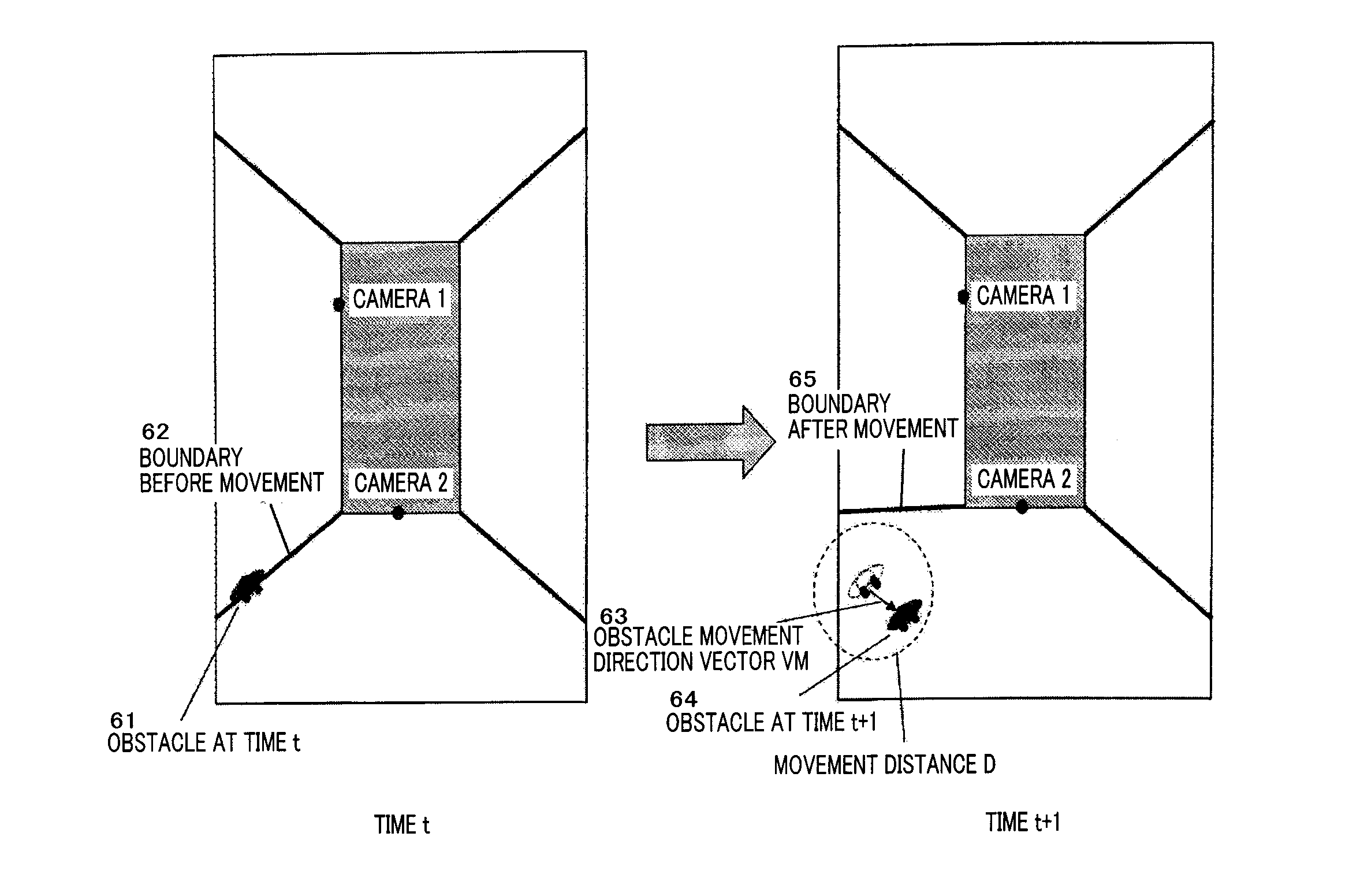
[0064]Obstacle movement direction prediction section 43 determines from an obstacle movement direction detected by obstacle detection section 42 and vehicle information 35 (shift information and steering angle information) of the vehicle movement information obtained by vehicle movement information acquisition section 46 whether or not an obstacle will enter the vehicle's path of travel from the obstacle's movement direction and movement velocity, and if such entry is predicted, obstacle movement direction prediction section 43 changes a boundary such that the obstacle and boundary do not overlap.

[0065]Operations whereby a boundary is changed based on an obstacle's movement direction and movement velocity and the vehicle's movement direction will now be ...


PUM


Abstract

Disclosed is a driving support display device that composites and displays images acquired from a plurality of cameras, whereby images which are easy for the user to understand and which are accurate in the areas near the borders of partial images are provided. An image composition unit (41) formulates a bird's eye perspective image on the basis of a mapping table reference unit (45) using images of the area around the vehicle acquired from a plurality of cameras (31). An obstacle detection unit (42) detects obstacles in the images acquired by the plurality of cameras (31). On the basis of the obstacle information detected by the obstacle detection unit (42), an obstacle trajectory prediction unit (43) predicts the trajectory of the obstacle and determines the borders so that the borders of the obstacle and the composite image from the plurality of cameras (31) do not overlap. The image composition unit (41) acquires necessary information from the mapping table reference unit (45) and creates a bird's eye perspective image in which the borders of the obstacle and the images from the plurality of cameras do not overlap.

Description

TECHNICAL FIELD[0001]The present invention relates to a driving support display apparatus using a plurality of cameras that image the area around a vehicle, and more particularly to a driving support display apparatus that combines a bird's-eye-view image of the area around a vehicle from images captured by a plurality of cameras.BACKGROUND ART[0002]In recent years, driving support display apparatuses that display a bird's-eye-view image giving a downward view of the area around a vehicle from a virtual viewpoint above the vehicle on a monitor have become increasingly popular. Many driving support display apparatuses generate a bird's-eye-view image using a plurality of cameras in order to cover a wide monitoring range.[0003]FIG. 1 is a drawing showing a camera arrangement in a driving support display apparatus and a bird's-eye-view image obtained from images captured by the cameras.[0004]As shown in FIG. 1, first through fourth cameras 11 through 14 are installed on vehicle 1. Firs...

Claims


Application Information

Patent Timeline
Patent Type & Authority Patents(United States)
IPC IPC(8): G06K9/00
CPCB60R2300/105B60R2300/607B60R1/00G06T2207/30261H04N7/181B60R2300/303G06T3/4038G06T7/004G06T7/246G06T7/70
Inventor KAMIYAMA, HIROTAKA
Owner PANASONIC CORP
Why Eureka
Try Eureka