Conveyance apparatus using movable body

Inactive Publication Date: 2005-08-25
DAIFUKU CO LTD
View PDF0 Cites 14 Cited by
  • Summary
  • Abstract
  • Description
  • Claims
  • Application Information

AI Technical Summary

Benefits of technology

[0008] Therefore, it is an object of the present invention to provide a conveyance apparatus using movable bodies, whereby spacing between movable bodies in the lateral direction can be mainta

Problems solved by technology

However, according to the prior art constitution described above, in the lateral travel path section, it is not readily possible to maintain a spacing between movable bodies in the lateral travel direction, and therefore, in order

Method used


Image

  • Conveyance apparatus using movable body
  • Conveyance apparatus using movable body
  • Conveyance apparatus using movable body

Examples


first embodiment

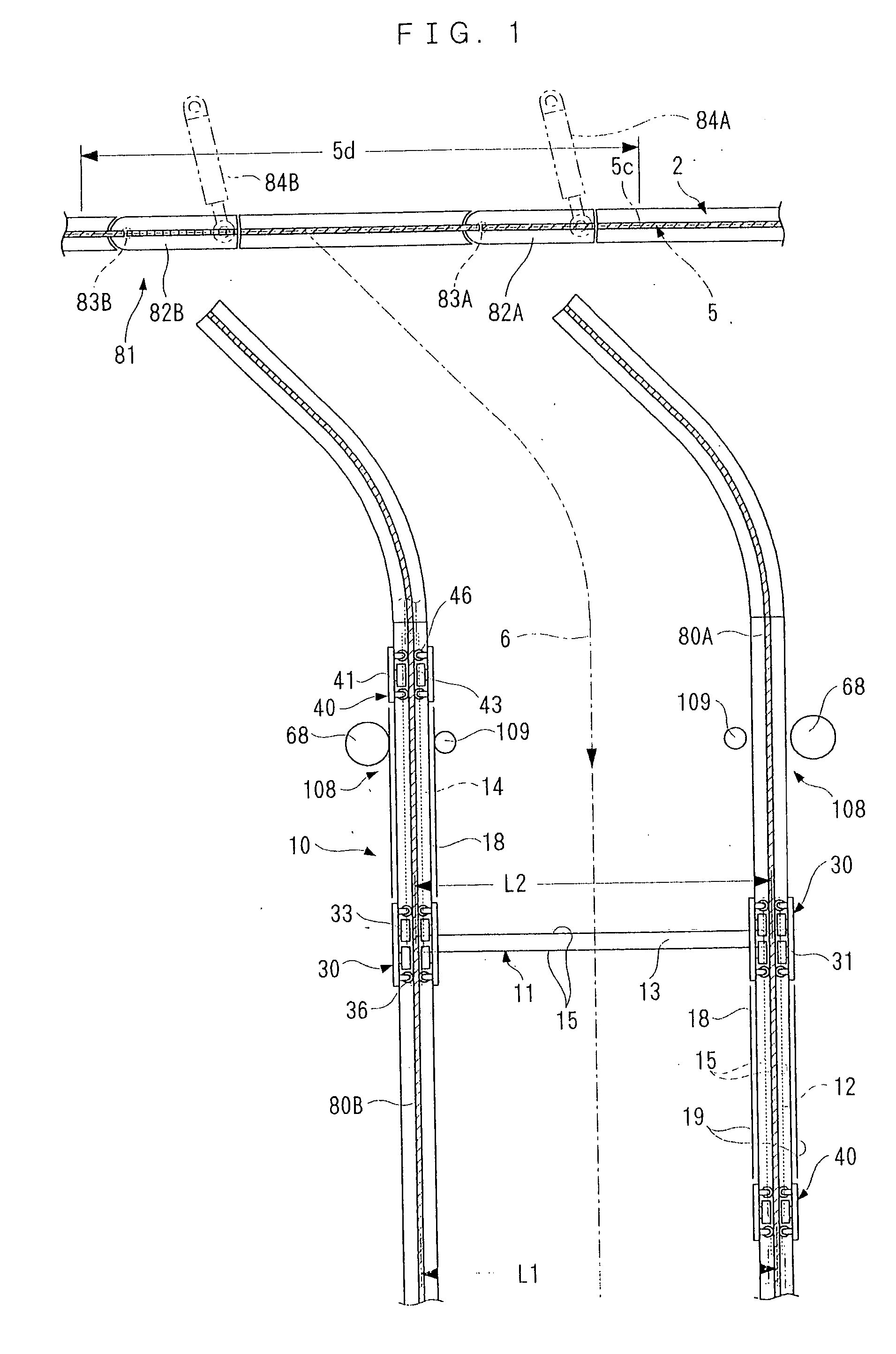
[0062] the present invention is described below in a mode applied to a ceiling-located travel system for movable bodies, with reference to FIG. 1-FIG. 20.

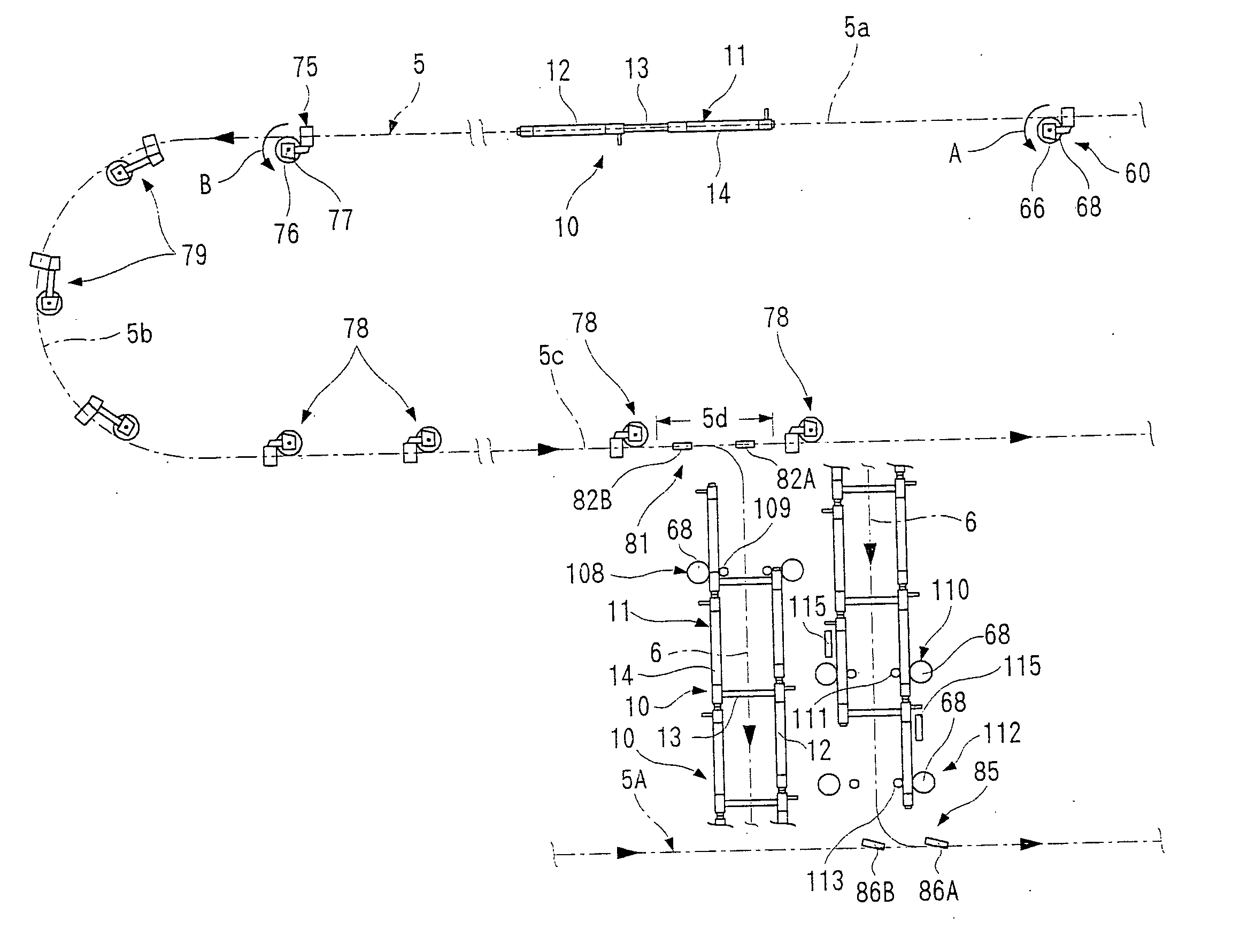
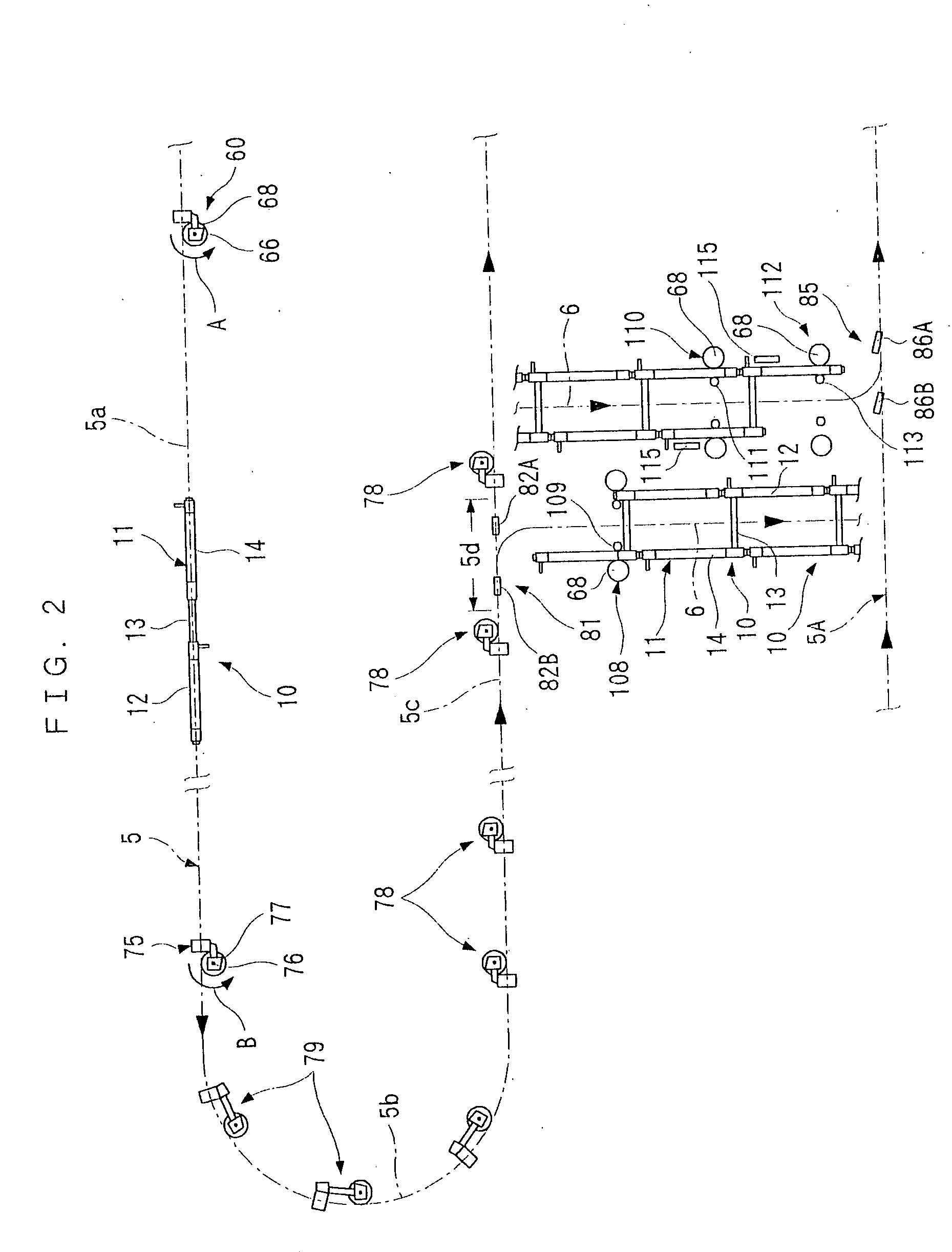
[0063] In FIG. 2 to FIG. 8, a main rail 2 having an I-shaped cross section is provided on a ceiling-mounted machine frame 1. This main rail 2 forms a fixed path 5. Here, the fixed path 5 comprises, in plan view, for example, a pair of parallel linear shaped path sections 5a, 5c, and a curved path section 5b which connects between the front and end portions of the linear shaped path sections 5a, 5c, and the like.

[0064] A portion of one of the pair of linear shaped path sections 5c is formed into a prescribed region 5d, and a working path section 6 is formed orthogonally on one side of this prescribed region 5d. Moreover, a separate fixed path 5A which is orthogonal to the working path section 6 and parallel to the linear path section 5c is similarly formed by a main rail 2A, or the like, having an I-shaped cross-section.

[0065] A m...

second embodiment

[0128] Next, the present invention is described on the basis of FIG. 21 toFIG. 24. More specifically, branching means 121 comprises two divided rail members 122A, 122B capable of supporting the guided devices 30, 40, formed by dividing the main rail 2 at a prescribed region 5d, and rotating devices 131A, 131B which cause these divided rail members 122A, 122B to rotate about vertical axes 123A, 123B. The divided rail members 122A, 122B are constituted in such a manner that when rotated and separated from the main rail 2, they can be connected to lateral travel rail members 80A, 80B.

[0129] In order to rotate the two divided rail members 122A, 122B about the vertical axes 123A, 123B, bearings 125A, 125B are provided on beams 124A, 124B, and the divided rail members 122A, 122B are connected to the lower end of vertical axles 126A, 126B supported rotatably on the bearings 125A, 125B.

[0130] The rotating devices 131A, 131B which cause the divided rail members 122A, 122B to rotate about th...

third embodiment

[0139] Next, the present invention will be described on the basis of FIG. 25 and FIG. 26.

[0140] In this third embodiment, a configuration of lateral travelling is achieved wherein a movable body 10 does not pass through the prescribed region 5d when it reaches it, but rather is always moved onto a working path section 6. More specifically, as illustrated in FIG. 25, the branching means 140 is provided in one place, commonly for both the lateral travel rail members 80A, 80B, and it comprises a rail member 141 which connects to the final end of the main rail 2, and an operating device (cylinder device, or the like) 143 for causing this rail member 141 to rotate about the axis of a vertical axle 142. A composition is adopted wherein when the rail member 141 is rotated, the upstream end thereof remains connected to the main rail 2 at all times, and the downstream end thereof connects selectively with one of the two lateral travel rail members 80A, 80B.

[0141] As illustrated in FIG. 26, ...


PUM


Abstract

A conveyance apparatus using movable bodies, in which a plurality of lateral travel rail members capable of supporting and guiding guided devices situated on a main rail are provided to the side of a prescribed region of the fixed path, in such a manner that a frame member provided with a supporting section assumes an orthogonal attitude or position with respect to a direction of travel, and the other frame members become aligned in the direction of travel, and causing the guided devices to branch off onto the lateral travel rail member group in the prescribed region. Thereby, spacing between the movable bodies in the lateral travel direction can be maintained readily by using a simple structure, and the group of movable bodies can be moved laterally in such a manner that there is no mutual contact between conveyed items.

Description

CROSS REFERENCE TO RELATED APPLICATIONS [0001] This application is a divisional application of application Ser. No. 10 / 601,447, filed Jun. 23, 2003.BACKGROUND OF THE INVENTION [0002] 1. Field of the Invention [0003] The present invention relates to a conveyance apparatus using movable bodies, which is used to move a movable body for conveying items on a fixed path located on a floor or on a ceiling, for example. [0004] 2. Background Art [0005] Conventionally, a conveyance apparatus using movable bodies disclosed in Japanese Unexamined Patent Publication No. 2001-114094, for example, has been used as this kind of apparatus. More specifically, the main body of a movable body which is able to move along a fixed path by being supported and guided on rails by means of a plurality of guided devices, is formed by three frame members which are connected, by means of a connecting device, in a relatively rotatable fashion in lateral directions traversing the longitudinal travelling direction ...

Claims


Application Information

Patent Timeline
IPC IPC(8): B61B13/00B61B3/00B61B13/12B61J1/10B65G35/00
CPCB61B3/00B65G35/06B61B13/127
Inventor KAWATO, KENICHIRONISHIHARA, SHIGEYOSHI
Owner DAIFUKU CO LTD
Why Eureka
Try Eureka