Interference mitigation apparatus and interference mitigation method for home network transmission line, and communication system using same

a technology of interference mitigation and transmission line, which is applied in the direction of line transmission details, orthogonal multiplexes, baseband system details, etc., can solve the problems of high replacement and modification costs, difficulty in achieving a speed of up to 200 mbps without increasing the number of pairs, etc., and achieves the effect of minimizing interference on a transmission line, minimizing interference in a transmission line, and minimizing large interferen

Active Publication Date: 2018-01-09
KT CORP
View PDF15 Cites 3 Cited by
  • Summary
  • Abstract
  • Description
  • Claims
  • Application Information

AI Technical Summary

Benefits of technology

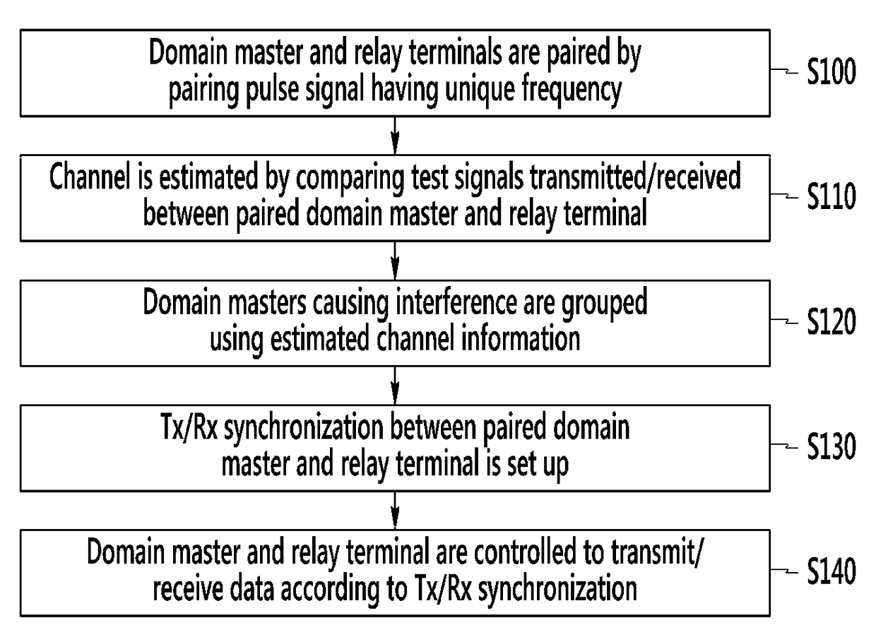
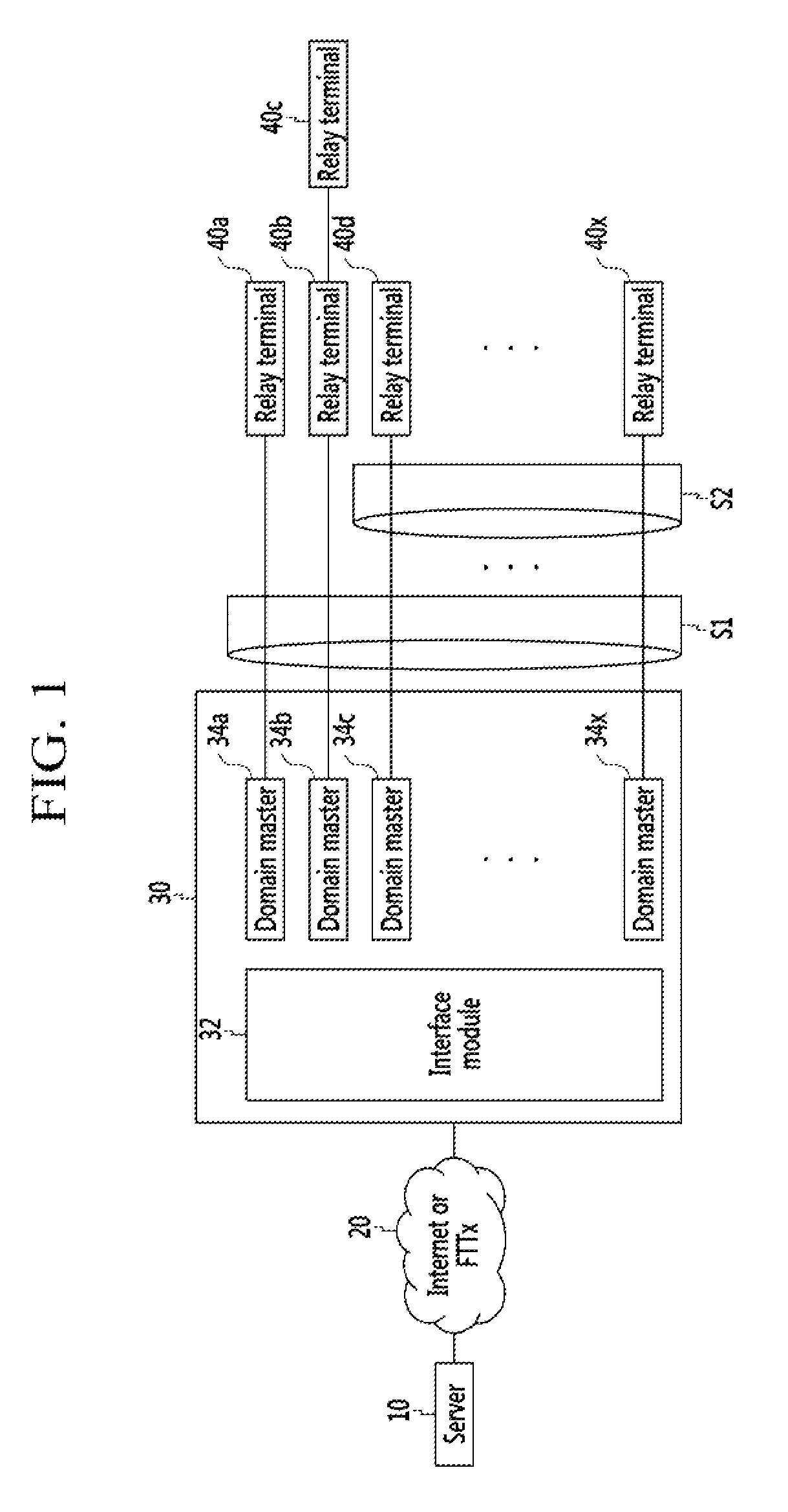
[0025]According to at least one embodiment of the present disclosure, interferences in a transmission line may be minimized by pairing domain masters and relay terminals through the pairing pulse signal selecting domain maters having comparatively large interferences based on a result of estimating channels, grouping the selected domain maters, and transmitting and receiving through the grouped domain masters.
[0026]In addition, according to at least one embodiment of the present disclosure, interference on a transmission line may be minimized by controlling domain masters and relay terminals to transmit and receive data according to Tx / Rx synchronization and by controlling domain masters belonging to the same group not to transmit and receive data at the same time.

Problems solved by technology

However, such a bonding technology requires at least two or more pairs.
Accordingly, it has been difficult to achieve a speed of up to 200 Mbps without increasing the number of pairs.
Such replacement and modification requires excessive cost.
However, in this case, it demands a method for mitigating interference in a wire bundle environment where interference noise is generated in a subscriber aggregation area.

Method used


Image

  • Interference mitigation apparatus and interference mitigation method for home network transmission line, and communication system using same
  • Interference mitigation apparatus and interference mitigation method for home network transmission line, and communication system using same
  • Interference mitigation apparatus and interference mitigation method for home network transmission line, and communication system using same

Examples


Embodiment Construction

[0033]In the following detailed description, only certain exemplary embodiments of the present disclosure have been shown and described, simply by way of illustration. As those skilled in the art would realize, the described embodiments may be modified in various different ways, all without departing from the spirit or scope of the present disclosure. Accordingly, the drawings and description are to be regarded as illustrative in nature and not restrictive, and like reference numerals designate like elements throughout the specification.

[0034]Throughout the specification, unless explicitly described to the contrary, the word “comprise” and variations such as “comprises” or “comprising” will be understood to imply the inclusion of stated elements but not the exclusion of any other elements. In addition, the terms “-er”, “-or” and “module” described in the specification mean units for processing at least one function and operation and can be implemented by hardware components or softw...


PUM


Abstract

Provided is a method for mitigating, by an interference mitigation apparatus, interference on a home network transmission line. The method includes pairing domain masters with relay terminals by a signal having a unique frequency, grouping the domain masters, performing Tx / Rx synchronization between the domain masters and the relay terminals, and controlling the domain masters and the relay terminals to transmit / receive data according to the Tx / Rx synchronization. The domain masters of the same groups may be controlled not to simultaneously transmit / receive data.

Description

CROSS REFERENCE TO RELATED APPLICATIONS[0001]This application is a National Stage Patent Application of PCT International Patent Application No. PCT / KR2014 / 009131 (filed on Sep. 29, 2014) under 35 U.S.C. §371, which claims priority to Korean Patent Application Nos. 10-2013-0143972 (filed on Nov. 25, 2013) and 10-2014-0115445 (filed on Sep. 1, 2014), the teachings of which are incorporated herein in their entireties by reference.TECHNICAL FIELD[0002]The present disclosure relates to an interference mitigation apparatus and an interference mitigation method for home network transmission line and communication system using same.BACKGROUND ART[0003]Typically, based on a very high bit rate digital subscriber line (VDSL) technology, an uplink / downlink frequency division multiplexing (FDM) scheme has been used for indoor telephone lines to achieve a transmission speed of up to about 100 Mbps by applying a maximum of about 30 MHz frequency band.[0004]In the related art, a bonding technology...

Claims


Application Information

Patent Timeline
Patent Type & Authority Patents(United States)
IPC IPC(8): H04B3/32H04B15/00H04L25/02H04L7/00H04B3/46H04B3/54H04L5/00
CPCH04B3/32H04B3/46H04B3/54H04L5/0048H04L7/0091H04L25/0204H04L25/0224H04L7/0079H04B15/00H04J11/0056H04L1/0001
Inventor PARK, NOWOOKPARK, HYUNG-JINJEONG, IN-TAEK
Owner KT CORP
Why Eureka
Try Eureka